Why?
Just when I thought it was safe to go back in the water - "Jaws 2"
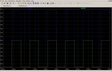
Or am I reading that chart wrongly. It seems to clip the tops out of the positive half of the wave at the correct level of about 10A.
But the negative half seems to cut at (-)60% of this value.
If this is the case then I will continue to read.
Do you have any idea why? - and I'm not asking you to go out and find the answer for me, because I am very resourceful and will get to the bottom of it.
If all else fails I will loose the limiter on the negative half or dump both for a simple pair of diodes over both halves on the output.
Cheers Cobber.
Here is a simulation of the VI limiter in action with a 0.001 ohm load.
Just when I thought it was safe to go back in the water - "Jaws 2"
Or am I reading that chart wrongly. It seems to clip the tops out of the positive half of the wave at the correct level of about 10A.
But the negative half seems to cut at (-)60% of this value.
If this is the case then I will continue to read.
Do you have any idea why? - and I'm not asking you to go out and find the answer for me, because I am very resourceful and will get to the bottom of it.
If all else fails I will loose the limiter on the negative half or dump both for a simple pair of diodes over both halves on the output.
Cheers Cobber.
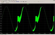
The circuit is not symmetrical - different things happen to the positive and negative halves of the output wave. It is possible to get things in balance as far as current limits go, but that brings a new problem. See post 61.
The only way to overcome this is a fully symmetrical circuit where everything is duplicated. See post 36.
The only way to overcome this is a fully symmetrical circuit where everything is duplicated. See post 36.
Last edited:
A new circuit
J: Can you suggest a better circuit to work on, or could I possibly cut 4 of the output devices off each rail of the circuit from post #36 and adjust the currents to suit that one. I think I can do this on my own by using the calculations laid out in the original design brief?
J: Can you suggest a better circuit to work on, or could I possibly cut 4 of the output devices off each rail of the circuit from post #36 and adjust the currents to suit that one. I think I can do this on my own by using the calculations laid out in the original design brief?
You could adapt that circuit to suit your needs, but of course your original design brief of simplicity goes out the window then. Laying out a PCB will be a real challenge. 😉
If you do take out some the output transistors, remember that the ability to drive really low impedance loads will be lost as well. All those trannies are there to pump out lots of current.
The circuit that we have above is quite good as long as you keep the load above 4 ohm, preferably at 8 ohm. Most commercial amplifiers have exactly this limitation, for the same reasons.
AFAIK there are very few off-the-shelf products that will drive loads at 2 ohm or below. Krell springs to mind.
Last edited:

I now have a new desktop graphic black and green (i think!). Actually I think I would rather face the music that that big White pointer, we have heaps of them nasty-buggers down here because they love eating the seals that loaf around on the rocks. They get really big and fat, but when they strike, they hit like a Mack truck, and the poor old seal is gone in a flash. I know this because I saw a documentary that was shot out off the Cape in your ocean which is essentially my ocean too.
One of the local Gov't bodies did a tag & release using rf transmitters on the dorsals of a few of them and over a period of about 4 weeks one of the three tagged animals had made his way right up to Queensland and then half way back. They may be fat, but they can really move. It is possible that some animals from the Cape have immigrated over here, thanks very much.
One of the local Gov't bodies did a tag & release using rf transmitters on the dorsals of a few of them and over a period of about 4 weeks one of the three tagged animals had made his way right up to Queensland and then half way back. They may be fat, but they can really move. It is possible that some animals from the Cape have immigrated over here, thanks very much.
I can remember seeing a documentary about the antics of the great whites in False Bay, but we digress. 😀
An externally hosted image should be here but it was not working when we last tested it.
If you mean this kind,the answer is a big thumbs up from my side.

For readers from other parts of the world:
For readers from other parts of the world:
Cadbury Flake is a bar of thinly folded milk chocolate produced in Britain, New Zealand, Australia, Ireland and South Africa by Cadbury.
Cadbury Flake - Wikipedia, the free encyclopedia
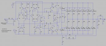
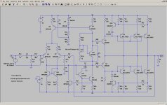
Back to the topic - here is the fixed version of the amp. The problem turned out to be the low-pass filter on the input. I am still sqeamish about publishing component values. If somebody blows up his workshop with this, who will be blamed? 
For a load of 0.5 ohm, power output is 1800W at 0.008% at 1kHz. Peak loak current is about 80A. Each transistor has a collector current of 14A, which is dangerously close to its limit of 17A. To build this thing you will need a 4kVA transformer. Such things tip the scale at 25kg. All in all, a much bigger thing than I'm willing to take on.
For a load of 0.5 ohm, power output is 1800W at 0.008% at 1kHz. Peak loak current is about 80A. Each transistor has a collector current of 14A, which is dangerously close to its limit of 17A. To build this thing you will need a 4kVA transformer. Such things tip the scale at 25kg. All in all, a much bigger thing than I'm willing to take on.
Attachments
Last edited:
Into 8 ohm, power is 160W with 0.008% THD at 1kHz. You could take off a few pairs of output transistors if you don't want to drive insane loads, but the extra complication of the preceding stages remain the same. Hardly worth all the additional effort if you ask me.
I think you are right, we will stick with this one and eventually the answers will all be revealed.
I just looked at the now obsolete chinese LJM-L12 Circuit, it is very similar to the one we are working on and the fact that it was on the market for just a short time seems to be a bad omen. In that design the VI Limiter was omitted , but it used a rectifier over each half of the the output to cover the short circuit scenario.
I just looked at the now obsolete chinese LJM-L12 Circuit, it is very similar to the one we are working on and the fact that it was on the market for just a short time seems to be a bad omen. In that design the VI Limiter was omitted , but it used a rectifier over each half of the the output to cover the short circuit scenario.
do you mean a pair of diodes connecting the output line to the supply rails or to the collectors/drains of the output devices?it used a rectifier over each half of the the output to cover the short circuit scenario.
Any similarities to the LJM-L12 circuit are purely coincental, hehehe. Just goes to show that there is not much new to invent in class B audio amplifiers using bipolar transistors....
Those two diodes from the load to the power rails are probably of little value when things go bang. Randy Slone and Douglas Self does not even mention this technique in their books.
In the meantime, here is another variation on your circuit. I added another pair of output transistors. It will now happily drive a 3 ohm load, which probably as bad as it gets with real speakers. Even the Linn Isobarik DMS (*) which was quite notorious in its time for needing just the right kind of amp did not go below that.
(*) For more on this speaker, see my thread http://www.diyaudio.com/forums/multi-way/192988-linn-isobarik-pms-clone-21st-century.html
Those two diodes from the load to the power rails are probably of little value when things go bang. Randy Slone and Douglas Self does not even mention this technique in their books.
An externally hosted image should be here but it was not working when we last tested it.
In the meantime, here is another variation on your circuit. I added another pair of output transistors. It will now happily drive a 3 ohm load, which probably as bad as it gets with real speakers. Even the Linn Isobarik DMS (*) which was quite notorious in its time for needing just the right kind of amp did not go below that.
(*) For more on this speaker, see my thread http://www.diyaudio.com/forums/multi-way/192988-linn-isobarik-pms-clone-21st-century.html
Attachments
Last edited:
This just in - THD at 20kHz, 150W into 8 ohm is 0.08%. Quite good, even if I say so myself.
One thing that we haven't looked at yet is the phase margin.
One thing that we haven't looked at yet is the phase margin.
Hi there Andy. Starting from the Negative rail the diodes 'point upwards'. one from neg rail to speaker output at the junction of the 2 x 0.22r powr resistrs. Another from that junction to the Positive rail.
Do you think this is a 'bad' idea?
Do you think this is a 'bad' idea?
- Status
- Not open for further replies.
- Home
- Amplifiers
- Solid State
- Engineer, help please - Neg. feedback/infilters