dlr said:Anyone with any understanding of distortion in drivers will recognize this. There's every possibility that it increases distortion in some area. Only measurements can provide the necessary evidence one way or the other. But the latter is possible, measurement systems have had this capability for many years.
Distortion is anything that isn't present in the original signal. That of course has to be weighted by the ear-brains sensitivity to distortion meachanisms (things that are natural are much easier to live with than things that aren't -- ie 2nd vrs 7th... even a little bit of 7th in annoying, even in the precense of large amounts of 2nd)
If electronics are any indication -- and i'd think that they are easier to qunatify than speakers -- we have a long long way to go before we have anything more than a modicum of understanding of anything but the grossest of distortions. And if we can't yet fullt quantify an amplifier i wouldn't think we have any hope of fully quantifying a speaker. So measurements don't offer any proof either, just clues.
take for example the late 70s. Lower and lower THD was touted as proof that a piece of electronics sounded better... we know how that worked out.
Now that Ron has a sim that gives an idea of what could be happening how do we measure to verify or refute?
dave
dlr,
Never said it didn't suppress distortion. Said I could not find any indication of quantity change, though I have seen some slight change in the various amounts found in specific orders of before and after distortion plots.
Just as I said I couldn't find what I thought was a significant change in frequency response. You were kind enough to show me what you think of as a significant change. I am still a bit doubtful of the significance of what you found, but I am not an expert in piston based test measurements. Something I have also pointed out many times. I am not qualified to run the tests you are certain will show all there is to know about an EnABL'd driver. I must defer to someone who can run these tests and satisfy your need for letter perfect test conditions and absolute adherence to piston theory limitations.
However, I can and do make the claim that I can and do reduce same frequency ringing and can and do allow greater uncompressed headroom for transient signals. Not playing louder from just the treatment, but able to play louder, by turning up the volume control, without experiencing the typical awful sounds that occur to an untreated driver as it's energy input exceeds it's ability to coherently get that energy out into the adjacent air and room..
I can claim this, I do claim this and I intend to continue claiming it. And I intend to continue showing other people how to treat specific drivers, with EnABL.
I am sorry this insults you to such a degree, but that is not my business or fault. I don't provide either my thoughts or treatment suggestions out of malice, cynicism or myopic religious fervor. I provide them because in every treatment but one, out of more than 300 speaker systems, with crossovers and multiple drivers, and the last few full range speakers, I have been able to provide the same qualities of sonic performance with respect to ringing, low level coherence, and dynamic excursion limitations, due to the onset of sonic uglies. These are EnABL treatments that I personally performed and for most of them, for other people, on their speaker systems, at their request, for free.
When tests arrive, from someone you can respect, we can go over them in detail and see if they provide a clue to what I and an increasing number of folks who actually follow my simple, straight forward instructions have attained. I hope for the sake of your sanity that we can find some evidence that at least leads us to what other avenues to explore.
But Dave, continuing to shout at me, about what I am allowed to do and claim I am doing, isn't going to move any of this any closer.
Have some patience please!
Bud
FOSTEX 120 A.
This is a very promising speaker, right out of the box. Clear and surprisingly unstrained presentation. Very nearly without any of the artifacts I have come to expect from aluminum anything, used in speakers. There are some propagation restraints that ended up being due to the semi soft ring glued to the surround, out at the joint with the basket, and this ring tends to add a slight localization to the speaker and a slight megaphone character.
Application of the same ring set used to cure this problem in the Hemp FR4.5's also cured it here. The entire picture collection that shows this ring application, and the others also, can be seen here.
All of the upper cone and outer ring blocks were applied with an inverted A4 calligraphy pen tip.
http://picasaweb.google.com/hpurvine/Fostex120A
The outer cone ring is standard fare, but the inner cone ring and dome ring have not been combined here. Experience with other drivers that have a viscoelastic glue deposited in the cone to voice coil joint caused me to apply two full sets of rings here. The usual 12 blocks, in six sets, in two rings is used to terminate the dome center and an 0.060" spot of paint with a slightly smaller than typical 0.040" dot of PVA on it, helps in dispersing the frequency response across the included angle of the cone. These are very wide dispersion speakers, with a very wide frequency response.
A bit of a pain to do these inner rings with an adequate guide ring. So I choose to provide one that you place on the dome and place the dome dots first using it as a guide. Then just use the dome dot's to provide placement of the cone dots. A bit crude in words, but easy and intuitive to perform. I used an #3/.80 Rapidiograph pen for all of the dots on lower cone and dome.
The gloss coating is very minimal and all of it is 50 % cut with water and gently stirred, not shaken. I applied three circumferential brush strokes, with a long side tamp back into the bottle. Each of these brush stroke moved up the cone surface and covered 1/4 of the cone circumference at that height, per stroke. After completing the final stroke per quarter, I went back and brushed radially up the entire cone, over the just painted quarter. I did not re dip the brush for this and also only applied a slight pressure, just enough to deform the brush to a very slight curve, The strokes were also pretty quick, as I wanted to catch and redistribute any banded collection of material before it seeped into this already filled cone. The original brush tamping was more than usual as I waited for all visible material, which is an opaque gray white, to run out of the brush before application to the circumferential strokes.
The center dome needs a tiny, fine haired brush, very well tamped on all sides. Then a light coating of gloss is applied over just the EnABL dot areas, out at the edge and a triangular area in the center. Leave the rest of the dome uncoated. A single sweep around the viscoelastic glue is adequate.
For the ring attached to the surround I applied a coat of 50% gloss before I put the EnABL patten down and another afterwards. This was the last step in opening the full frequency response out to the included angle of the cone and eliminating any vestige of hot spot right over the dome, though there is still a slight increase in high frequencies in this area. I also applied the typical dry brush application of gloss onto the surround. Doing so after the second coating was applied to the outer rings and the brush was almost exhausted. Apply no pressure here, just allow some of the remaining gloss to rub onto the surface of the surround. You absolutely do not want to use a full or partially charged brush here, just a little icing on the surface and not much of it either.
Sitting nude on the usual stands these are clear and clean drivers with likely the best micro dynamic coherence I have ever heard. Also unusually sweet throughout the frequency range, very fast and more agile in reproducing orchestral and choral activities than all but a small handful of other drivers I have treated, full range or other. If you have these and want to treat them, after suitable experience with speakers you do not care about, I can highly recommend the results.
Attached is a PDF of the pattern rings and the typical conic section showing approximate placement, though the lower rings should be placed closer to the voice coil than this conic section shows. Follow the pictures in this respect. The red paint for the patterns was a specific request of Jim Rebman, who asked me to treat these for him. You can use what color suits you, but I really, very strongly urge you to use the Poly S flat acrylics on this driver, rather than an ad hoc substitute.
Bud
Attachments
Kaan. The relationship of blocks to open space is as follows.
ok
but I really, very strongly urge you to use the Poly S flat acrylics on this driver, rather than an ad hoc substitute.
So I need to get some proper paint as well when I go shopping 🙂
BudP said:dlr,
Never said it didn't suppress distortion. Said I could not find any indication of quantity change, though I have seen some slight change in the various amounts found in specific orders of before and after distortion plots.
My post was triggered by the unqualified statement that "suppressing the non signal generated ringing, that EnABL is set up for". That was specific and relates to frequency response and distortion. Qualifying a post with "I don't know specifically what's happening, but..." would be more correct. Anyone reading the post would read it as unequivocal on the effects, in this case, distortion.
Just as I said I couldn't find what I thought was a significant change in frequency response. You were kind enough to show me what you think of as a significant change. I am still a bit doubtful of the significance of what you found, but I am not an expert in piston based test measurements. Something I have also pointed out many times.
Here we come full circle. There cannot be a change in the output of a driver without a change in the frequency response and/or distortion signature.
However, I can and do make the claim that I can and do reduce same frequency ringing...
I and others have always agreed that this may indeed occur with any mod to a diaphragm.
I can claim this, I do claim this and I intend to continue claiming it. And I intend to continue showing other people how to treat specific drivers, with EnABL.
I would not and do not take issue with the claims as you've stated them to "reduce some frequency ringing". This may indeed occur as has been said more than once by myself and others, all discussion of mechanism aside. It won't, however, "suppress the non signal generated ringing" (i.e. distortion, non-signal generated being primarily motor and IMD), again as you said "that EnABL is set up for". One has to take the words in a post as written. An unqualified comment such as that throws up a red flag. What would you expect a reasonable participant in a discussion is going to do when such a comment is made?
Dave
MJL21193 said:
Hi,
When did you take it? You have a screen shot?
I hung a screen shot of it up on the wall, right next to my high school diploma. 😀
Hi dlr,
Do you appreciate that
"suppressing the non signal generated ringing"
refers to air-side energy already transduced but not yet dissipated and which has become independent of on-going voice coil drive ?
A driver has two frequency responses you know ?
(1) The intial response where it not only attempts to generate the 'listeners' wave, but also *loses* energy to charging up all losses and energy storage mechanisms (air-spring resonances etc.)
(2) The steady response with a constant sine, after all charging and energy storage/release mechanisms have stabilised.
Those air spring mechanisms then modifying on-going waveforms or releasing their energy when the waveform changes or stops.
Are CSDs at zero on the time axis identical to a steady sine amplitude measured frequency response, or do they already show up the dips where energy is sucked out into various storage modes ?
The difference between responses (1) and (2) must relates to stored energies which then colour or cloud reproduction.
So we need to be very careful about which frequency response is being discussed here as per your questioning whether distortion is linear or IMD -
? on continuous sine ?
Sadly, when it comes to frequency response and distortion the 'theory' exponents tend to think in terms of (2) only !
For the storage mechanisms must charge too, and this affect reproduction.
Cheers .......... Graham.
This is truely an issue when it comes to measurement techniques and how useful data can be used in the process of improving a product. I have measured some drivers that differ significantly using Sine sweep and MLS. A very educating experience. People who don't know what to make if the difference wanted to accept the better looking Sine sweep results for sales purposes.Graham Maynard said:Hi dlr,
...
So we need to be very careful about which frequency response is being discussed here as per your questioning whether distortion is linear or IMD - ? on continuous sine ?
Sadly, when it comes to frequency response and distortion the 'theory' exponents tend to think in terms of (2) only !
Cheers .......... Graham.
staggerlee said:
I hung a screen shot of it up on the wall, right next to my high school diploma. 😀
Good for you.
Have you heard the expression: "talking through your hat"? I think it applies here.
Graham Maynard said:
Are CSDs at zero on the time axis identical to a steady sine amplitude measured frequency response, or do they already show up the dips where energy is sucked out into various storage modes ?
Cheers .......... Graham.
Sorry Graham, but this is what I love about this thread. People expounding about differences in measured results when they don't understand what the measurement is in the first place.
appreciated nonsense
has anyone considered the possibility that this may somehow influence the flux surrounding the "air-springs", thus enhancing the ommniprescient modulation of the "ether"? perhaps a phenomenologically induced anomaly?
Then again, maybe Fick's second law applies as well, eh?
just some more idle speculation
John L.
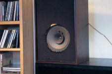
I did get a pair of new victims as well. This time they have a whizzer that will be a challenge for my new painting skills 😀
They are on the amp now and sound much better than they should, especialy in the high end frequency. They do however lack a lot in the deep registers.
So Bud I hope you will photoshop this image with your virtual EnABL so I'm sure that I get it right.
Thanks in advance 🙂
They are on the amp now and sound much better than they should, especialy in the high end frequency. They do however lack a lot in the deep registers.
So Bud I hope you will photoshop this image with your virtual EnABL so I'm sure that I get it right.
Thanks in advance 🙂
Attachments
Hi John k,
Thanks for that, but no need to say 'Sorry' to me, we all seek the same objective answer.
Just doing my best to make suggestions and prompt diverse thoughts, and asking questions which might promote thought/comment.
_________________________________________________
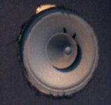
This is a driver pic I have in my photos folder without any caption.
Surely the 'phase plug' here has been designed to re-direct transverse wave pressures/velocities arising at the cone centre wrt circumference, instead of them colliding/interfering with voice coil induced cone motion.
Cheers .......... Graham.
Thanks for that, but no need to say 'Sorry' to me, we all seek the same objective answer.
Just doing my best to make suggestions and prompt diverse thoughts, and asking questions which might promote thought/comment.
_________________________________________________
This is a driver pic I have in my photos folder without any caption.
Surely the 'phase plug' here has been designed to re-direct transverse wave pressures/velocities arising at the cone centre wrt circumference, instead of them colliding/interfering with voice coil induced cone motion.
Cheers .......... Graham.
Attachments
Looks like someone put "Kisses" there.😀 It sure looks like the middle of a ring radiator tweeter as well.Graham Maynard said:Hi John k,
Thanks for that, but no need to say 'Sorry' to me, we all seek the same objective answer.
Just doing my best to make suggestions and prompt diverse thoughts, and asking questions which might promote thought/comment.
_________________________________________________
This is a driver pic I have in my photos folder without any caption.
Surely the 'phase plug' here has been designed to re-direct transverse wave pressures/velocities arising at the cone centre wrt circumference, instead of them colliding/interfering with voice coil induced cone motion.
Cheers .......... Graham.
dlr,
It has taken a while to unearth these plots, They are from a 6.5 inch Dyna Vox mid woofer, that is still for sale. I found them to be pretty inconclusive, at least to my untrained eye. Or, what I would consider very minimal differences, provide rather large scale differences, to a listener in the sound field.
In the PDF, the top file is the untreated driver plot. I will post the original bmp files, from Liberty Audio if you prefer them to the PDF.
I was not going to claim to have this test data if I could not find it, finding these took re installation of an obsolete hard drive. I will see if I can restart the lap top that these were originally from, to see if there is more data available.
Bud
Attachments
Hi Bud.
The kind of distortion plot shown here illustrates the manner in which distortion changes non-linearly with loudspeaker drive.
(John L's mention of Fick's 2nd Law ?)
Would be nice if the full EnABL process could deliver an improved set of figures/curves.
http://www.audio-club.de/text.php?id=90&s=read
German > English translation available via the Babel Fish window.
http://babelfish.altavista.com/
Cheers .......... Graham.
kaan,
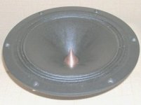
It will take a day or more for me to have enough time to provide patterns. This is going to be a much more difficult driver to treat. Shows some promise though, I like the voice coil dome and the ledge on the whizzer can be used to advantage too. You may have to obtain some acrylic always sticky paper glue from a craft shop or paper supplier. to use as actual damping material on the backside of the whizzer
Were I treating these, I would take five to seven days, applying specific pattern sets in order and listening to the effects for specific clues before proceeding. I don't think this forum would be the best place for this sort of communication because of how long my explanations are likely to get, but I am willing if you are. You might want to read the treatment posts for the Hemp FR8 driver and you really must read the tutorial first, just to get an idea of how complex this could get.
These are the Hemp FR8 posts
http://www.diyaudio.com/forums/showthread.php?postid=1359745#post1359745 post 1039
http://www.diyaudio.com/forums/showthread.php?postid=1363694#post1363694 post 1049
http://www.diyaudio.com/forums/showthread.php?postid=1364505#post1364505 post 1060
http://www.diyaudio.com/forums/showthread.php?postid=1367676#post1367676 post 1094
http://www.diyaudio.com/forums/showthread.php?postid=1371260#post1371260 post 1107
This is a tutorial for EnABL that you should read. See pages 8 and 9 for the tutorial.
http://www.hawthorneaudio.com/forums/viewtopic.php?f=2&t=1429&st=0&sk=t&sd=a&start=105
Bud]
- Status
- Not open for further replies.
- Home
- Loudspeakers
- Multi-Way
- EnABL Processes