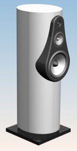
I'm toying with different enclosure designs and came up with an elliptical enclosure with a minimal protruding baffle. Are there any inherent reflection/diffraction issues with an ellipse when the voice coils are outside the actual ellipse?
It's a CNC cut sandwich design, so I've got a lot of freedom regarding bracing and just about anything else. I have a feeling the alternating "spikes" will help even if their size is random, but it'd be a lot easier to leave them out.
I'll be running digital crossovers and room correction/equalizing on a dedicated PC, so it'll be relatively simple to correct for baffle step an all that, but internal reflections are still a bad thing...
Comments?
Attachments

Hi,
FWIW a driver mounted centrally on the end of a cylinder is not good
for diffraction induced ripple, so not that good for the tweeter or bass.
Varying path lengths smooths the ripple.
rgds, sreten.
FWIW a driver mounted centrally on the end of a cylinder is not good
for diffraction induced ripple, so not that good for the tweeter or bass.
Varying path lengths smooths the ripple.
rgds, sreten.
By varying path lenghts do you mean ellipse vs circle, the "spikes" I've added, or something else?
The enclosure will be divided between bass and mid, so they'll have separate enclosures.
The enclosure will be divided between bass and mid, so they'll have separate enclosures.
Also, the baffle you are mounting the drivers on will not help control diffraction. If you go the trouble of making those nice elliptical baffles, try to mount them directly on them, by flattening a part of the elliptical baffle. Those nice round edges (in fact no edges at all) will do miracles.
D'oh! I was afraid of something like that... The problem is that flattening the ellipse will more or less remove the elliptic shape all together, unless it's wide as a small country. But the basic concept of having a huge baffle radius can be exploited in different ways. I'll be back!

Uhm - no, I won't... I was working on variable blends from the baffle to the main ellipse, but I don't have the skills in 3D curves to do that. So I think I'll choose to listen to the comment that suits me best 🙂
But back on topic - any comments on internal design?
But back on topic - any comments on internal design?
Last edited:
any comments on internal design?
The offset triangular pattern on the walls should dissipate mid-high to high frequency back waves but I'm sure that stuffing would do this just as well and some lower frequency too.
As for bracing, it should need more than a cylindrical chamber, as there is an unequal distance from the centre to the 'sides' - the flatter sides will be more susceptible to a lower frequency resonance.
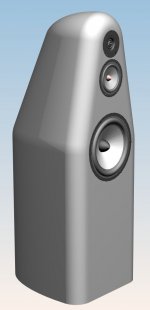
How about this one? The flattened front and back are just wide enough for the mid and a 30 mm blend, so bulges for the woofer seem like a decent tradeoff. The flats should be good for standing waves, too, so I can skip the triangles. It's far more volume efficient, too.
It's not quite as flashy as the original design, and looks a lot like designs I've seen before, but neither of those are necessarily bad...
It's not quite as flashy as the original design, and looks a lot like designs I've seen before, but neither of those are necessarily bad...
Attachments
It looks better than the first in my opinion.. What happens if you make the radius of the edges larger?
Not really useful... pretty though.
Once you have a sharp discontinuity, you no longer have much benefit from a fancy shape.
The original one was worse - the drivers sat off the "shape" and have very little distance before a sharp discontinuity occurs.
The whole point of something like an elliptical baffle is to minimize sharp discontinuities...
You mentioned a large baffle - note what an "IEC baffle" consists of. Note the frequency response obtained? Smaller baffle, not as flat or smooth a response. All smaller baffles are therefore some degree of compromise.
Look into "edge diffraction" as well... and "baffle step".
The aesthetics are one thing, the acoustics are another, combining the two is tricky...
😀
_-_-bear
PS. ok you know about baffle step... EQ'ing is not always a viable solution, btw... you also have floor bounce to contend with...
PPS. the internal "teeth" will not dissipate the HF, it will maybe diffuse the reflections though. At lower freqs you'll have the usual resonances that occur inside an enclosure, especially the top to bottom "pipe" resonance... no free lunch in acoustics! 🙁
Last edited:
SunRa: Thanks! After looking at the two designs some more, I agree. The blends can't go any further into the baffle than the mid driver, so in order to make the radius considerably larger I'd have to widen the baffle, which makes it look a lot boxier. I got it up to 40 mm radius without noticably changing the appearance.
bear: I tried to learn a lot of baffle theory a while back, but I gave up... I doubt the elliptic sides will do much more than add stiffness and looks, but the 40 mm edge blend should be a plus.
The internal bracing should help break things up a bit, and because of the midrange enclosure taking up half the space in the top it divides the top to bottom distance in two. I'll get renderings tomorrow, I'm too tired to explain properly 🙂
Bear's right the first edge the sound wave hits is the one you want to be a wide curve, the sides and back having a curve won't make much difference, and the bumps on the inside are essentially invisible to anything but the highest treble. Both of these things have related reasons - high frequency waves are short but mid and low frequency waves are pretty long. For rounded cabinet edges or internal teeth like that to have an effect they have to be an appreciable fraction of the wavelength in question. A 1kHz wave is over 30cm long, if those teeth or round overs are under 5cm the wave won't even "see" that it's there.
Last edited:
There after been a number of discussions about internal cabinet shapes lately. My opinion is that a cabinet lightly filled with fiberglass will have no internal effects for nearly any internal shape. Concentrate on the outside!
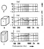
I'd recommend you find a copy of Olson's original paper on diffraction from various cabinet shapes. The attached image shows typical effects of a few different shapes. Note that he didn't use rounded corners but still got good response from a 45 degree set back.
You second shape looks like it would work well. Although your first shape has a well rounded cabinet contour, you have placed the drivers on a sharp edged protruding from the baffle. Not good for diffraction.
Good luck.
David S.
Attachments
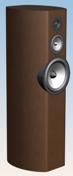
I have to admit the ellipse shape is mostly for show... From all the other threads I've read a 40mm radius blend will at least do something for the higher notes. A blend on top would of course be nice, but that would make it a lot more difficult to apply the wood veneer.
I'm attaching a render of the internal workings. The lower braces are self explanatory. The middle ones have an added crossmember for bracing the woofer magnet. The two upper ones have partial floors and walls to create separate enclosures for mid and tweeter (I'm using a Vifa XT25 without rear chamber). The irregularities of the braces and top enclosures should do at least something for breaking up the waves.
My initial suggestion for dampening is as follows:
Random angled wood cuttings glued to the bottom
Fibre glass stuffing in the rest of the bottom section
Fibre glass stuffing in the mid and tweeter enclosures
50 mm Glava sound mat (glass based Rockwool) top and back
50 mm Glava on top of the bottom brace
Attachments
One other comment I would make for anyone interested in cabinet effect is that you can mock up and measure them pretty easily. Thin cardboard taped to a square enclosure will let you try laid back wings at any angle. Chunks of styrofoam glued to a test cabinet will let you experiment with a variety of formed radiuses.
The point is that you don't have to build up a dense wooden enclosure to try some shapes for mid and HF diffraction effects, even thin carboard will work for testing at those frequencies.
The corner radius will help a little bit, but the ellipse is, as you say, just for show. In my experience a transition to a 30 degrees angled back side wings will give the best response. Unequal path lengths to each edge is also very important.
David S.
M'kay, so a slight offset for mid and tweeter would be benefitial?
Yes, download the program "The Edge" and experiment with a tweeter and its distance to top and sides. Careful choice of offsets will really make a difference.
David S.
Yes, download the program "The Edge" and experiment with a tweeter and its distance to top and sides. Careful choice of offsets will really make a difference.
David S.
Do you have a link for this? I can't find it. Thanks!
- Status
- Not open for further replies.
- Home
- Loudspeakers
- Multi-Way
- Elliptical enclosure - reflection/diffraction issues?