I'm modding a power amp with a schematics attached to improve the sound quality. It has speaker DC voltage protection, so I'm looking for options on eliminating an input DC blocking cap C5025.
DC voltage on the positive lead of C5025 is a few mV, but on the negative lead is -0.1V w.r.t. ground. If I short C5025, I'm getting +0.1V DC on the speaker output instead of 0V DC.
Are there ways to properly DC bias this amp after eliminating an input DC blocking cap C5025 without re-designing its schematic much?
Attachments
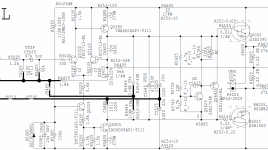
What is R5805 for?
Don't leave out the cap, but replace it with a shiny green 47uF Nichicon Muse BP. Also replace C6425 (feedback cap) with a 220uF 25V (or higher) Muse.
Don't leave out the cap, but replace it with a shiny green 47uF Nichicon Muse BP. Also replace C6425 (feedback cap) with a 220uF 25V (or higher) Muse.

R5805 is marked as 'NC'. It's not actually mounted.What is R5805 for?
Why? 🙂 AFAIK, there's at least one option to leave it out: DC servo like on this schematic. However, I'm looking for ideas on something less complex.Don't leave out the cap
In my experience, bipolar electrolytes sound awful. I'd rather stick in some combination of paralleled Nichicon FG, FW, Panasonic FM and, maybe, WIMA MKP 10 🙂replace it with a shiny green 47uF Nichicon Muse BP.
Yes, all caps have to be replaced here 🙂Also replace C6425 (feedback cap) with a 220uF 25V (or higher) Muse.
I believe I saw multiple BJT power amp designs in magazines of 1980 - 1990 years,(just haven't done digging yet). I hope not all of those designs utilized FET input 🙂BJT input requires a DC blocking capacitor.
I remember the lack of electrolytes in the signal path was a must-have and distinctive feature of what was considered a Hi-Fi amp those days 🙂
DC decoupling is the way to go when connecting audio blocks so each block has it's own DC path well controlled and isolated from the previous block (pre-amp, equalizer etc).
In addition, if right before this amp there is a potentiometer, you really need to eliminate any DC, otherwise you might have noise and strange behaviour each time you turn up and down the pot.
In addition, if right before this amp there is a potentiometer, you really need to eliminate any DC, otherwise you might have noise and strange behaviour each time you turn up and down the pot.
ron68
For implementing DC decoupling between blocks or leaving it out, all pros and cons should be carefully weighed in each individual case, each individual design, preference, etc.
I'm a fan of the 'the best cap is no cap' principle.
This is not like this in my specific case, i.e. no potentiometer in front of the amp or anything else I could think of. Actually, I've been testing this whole concept for many days in real world with the cap shorted and having those 100mV of DC on speakers and everything works just great.
So, there seems to be no point from the engineering standpoint in this specific case in having that cap in signal path provided that I would be able to figure out and implement a proper DC biasing of the amp.
Just to point out that there's no a single '100% right' answer for this problem, if we'd do a search, there have been people (this forum included) from both the 'to DC couple or not to DC couple' camps for many years, for example, just one of many 12 year old topic.
DC decoupling is the way to go when connecting audio blocks so each block has it's own DC path well controlled and isolated from the previous block (pre-amp, equalizer etc).
For implementing DC decoupling between blocks or leaving it out, all pros and cons should be carefully weighed in each individual case, each individual design, preference, etc.
I'm a fan of the 'the best cap is no cap' principle.
In addition, if right before this amp there is a potentiometer, you really need to eliminate any DC, otherwise you might have noise and strange behaviour each time you turn up and down the pot.
This is not like this in my specific case, i.e. no potentiometer in front of the amp or anything else I could think of. Actually, I've been testing this whole concept for many days in real world with the cap shorted and having those 100mV of DC on speakers and everything works just great.
So, there seems to be no point from the engineering standpoint in this specific case in having that cap in signal path provided that I would be able to figure out and implement a proper DC biasing of the amp.
Just to point out that there's no a single '100% right' answer for this problem, if we'd do a search, there have been people (this forum included) from both the 'to DC couple or not to DC couple' camps for many years, for example, just one of many 12 year old topic.
Add something that injects about 1.8 uA of DC current to the base node of Q5125 and the output will be at 0 V again.
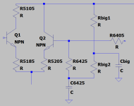
When you change the order of C6425 and R6425, so C6425 becomes a capacitor to ground, and connect C6425's negative pole to ground, then a big resistor from the supply to the node C6426/R6425 could do the trick. C6425 then filters any ripple current through the big resistor. If the hum is nonetheless unacceptable, you can split the big resistor into two equal parts and add an extra capacitor to ground at the midpoint.
When you change the order of C6425 and R6425, so C6425 becomes a capacitor to ground, and connect C6425's negative pole to ground, then a big resistor from the supply to the node C6426/R6425 could do the trick. C6425 then filters any ripple current through the big resistor. If the hum is nonetheless unacceptable, you can split the big resistor into two equal parts and add an extra capacitor to ground at the midpoint.
Last edited:
C6425 provides DC (de)coupling of the feedback signal and is in the feedback signal path. So that one must then also be eliminated.
Just short it, but then re-balance the DC conditions again to get zero offset.
A servo can probably not be avoided.
Jan
Just short it, but then re-balance the DC conditions again to get zero offset.
A servo can probably not be avoided.
Jan
I'm feeling the Muse, especially that green one, having read it looks like nothing on the kind of tester people get planes to access. It doesn't even cost a single coin. Though while paying the postage, the idea a 1uf+ plastic cap could also be tried.. well.. you could fit a switch and have both.
You plan to modify an amplifier, which schematic shows a primitive design with many bad decisions, and yet worry about the DC blocking capacitor because in your imagination this capacitor sounds bad.
The DC blocking capacitor has been scientifically proven to be a non-issue if done correctly, i.e. with large enough capacitance, bi-polar electrolytics. Done correctly, distortion is below measurement threshold.
You are even willing to introduce risky solutions to fix a non-issue that may cause significant DC bias in case of failure that may destroy your loudspeakers.
Fascinating how such pseudo science won't disappear despite debunked by proper science.
2 x 4.7 µF 50V Wima MKS2 in 5 mm pitch and you are OK. These are "DC fuses" and last in the chain protecting from sources that one day decide to identify as a battery. Also no servo of a DC coupled source can make the amplifier becoming crazy (think about that one). 100 mV offset on the loudspeaker is also not worth it.
Never omit these. Omit them in the stuff before the power ampifier at will (WITH thought) certainly if the preamplifier/buffer has both input and outputs caps and sources that have outputs caps. Yes I understand where you are coming from. The lack of standardization among designers make that often 2 caps in series occur. Clever people make silly mistakes too. It would be have been so much easier if caps would be used only at inputs and outputs DC coupled. Just like the chinese brands do now which is way better.
If C5005 is ceramic replace for film types. C6425 for MUSE ES bipolar caps. These don't sound awful, they are fine. Fight that cap-fobia, brother! The medicine is worse than the illness, it is just between the ears. Before you know it you'll have a second fobia or dogma.
Last edited:
If you don't want the input cap, you have to build a DC servo to constantly compensate the DC on output.ron68
For implementing DC decoupling between blocks or leaving it out, all pros and cons should be carefully weighed in each individual case, each individual design, preference, etc.
I'm a fan of the 'the best cap is no cap' principle.
This is not like this in my specific case, i.e. no potentiometer in front of the amp or anything else I could think of. Actually, I've been testing this whole concept for many days in real world with the cap shorted and having those 100mV of DC on speakers and everything works just great.
So, there seems to be no point from the engineering standpoint in this specific case in having that cap in signal path provided that I would be able to figure out and implement a proper DC biasing of the amp.
Just to point out that there's no a single '100% right' answer for this problem, if we'd do a search, there have been people (this forum included) from both the 'to DC couple or not to DC couple' camps for many years, for example, just one of many 12 year old topic.
And if this amp is to be connected to a generic source (CD, eq, pre-amp etc) this must be a control and not a fixed adjustment, since depending on the block you will connect to the amp, different DC level might show up on the input. And also other variables, such as temperature.
And if you choose to feed from a fixed DC coupled pre-amp (no caps), you still need the DC servo, since now the problem is transfered to the pre-amp - it will depend on the source you will connect to the pre-amp (DAC, CD, PC, smartphone etc).
Regarding the cap principle, did you stress your own blind test?
Ask some one to open and short the input cap so you can truly judje if you really hear the difference.
And this must be done on statistic basis: make, let's say, 20 times the test and take note of the results.
If you are right by, let's say, 90/10% on the results, ok, so you are able to hear.
But if you get 50/50%, 40/60%, it means it doesn't matter.
My principle is more pragmatic in everything I design: if we can hear/measure, it matters. If we cannot, it doesn't matter, despite of what others say.
If there’s one thing that can be said for that amplifier, is that it’s simple. And you want to add a complex DC-servo? Doesn’t make sense to me.
I’m a bit of an audio noob. What exactly are you worried that cap will do to your signal quality? You’d have a corner frequency of that DC filter that’s <1Hz, so flatness shouldn’t be a concern.
I’m a bit of an audio noob. What exactly are you worried that cap will do to your signal quality? You’d have a corner frequency of that DC filter that’s <1Hz, so flatness shouldn’t be a concern.
If you can drive your speaker with DC it helps to move a heavy box 😎
Jan
Jan
MarcelvdG, thank you! That's exactly the direction I was thinking to move to when starting this thread, but wasn't sure if it's a viable one!Add something that injects about 1.8 uA of DC current to the base node of Q5125 and the output will be at 0 V again.
When you change the order of C6425 and R6425, so C6425 becomes a capacitor to ground, and connect C6425's negative pole to ground, then a big resistor from the supply to the node C6426/R6425 could do the trick. C6425 then filters any ripple current through the big resistor. If the hum is nonetheless unacceptable, you can split the big resistor into two equal parts and add an extra capacitor to ground at the midpoint.
If I got your description correctly, the proposed circuit should be like the attached one, correct?
Then, the first issue is that the amp has dynamic power rail voltages depending on the 4 and 8 Ohm loads. Those could be either +/-24V, or +/-54V. So, the first idea I've got is to add a Zener diode in parallel to Cbig. Does it look good or there's something else you could think of?
Attachments
Last edited:
Jan, thank you! Shorting C6425 was the next on my list of eliminating caps here 🙂C6425 provides DC (de)coupling of the feedback signal and is in the feedback signal path. So that one must then also be eliminated.
Just short it, but then re-balance the DC conditions again to get zero offset.
A servo can probably not be avoided.
Jan
Would you mind elaborating on the changes to this schematic worthwhile trying for re-balancing the DC conditions after shorting C6425, but before going the servo way?
- Home
- Amplifiers
- Solid State
- Eliminating an input DC blocking cap