A servo is a hidden coupling cap.A servo can probably not be avoided.
Nothing more
nothing less

Oh it's more than that. It's additional complexity, noise sources and things in the feedback loop that can misbehave and cause oscillation. Don't sell it short! 🙂A servo is a hidden coupling cap.
Nothing more
MarcelvdG, thank you! That's exactly the direction I was thinking to move to when starting this thread, but wasn't sure if it's a viable one!
If I got your description correctly, the proposed circuit should be like the attached one, correct?
Then, the first issue is that the amp has dynamic power rail voltages depending on the 4 and 8 Ohm loads. Those could be either +/-24V, or +/-54V. So, the first idea I've got is to add a Zener diode in parallel to Cbig. Does it look good or there's something else you could think of?
Sounds like a good idea. With a Zener diode, you will have to reduce Rbig1 to get the current through the Zener in the range where it works. They are usually specified at currents of the order of 1 mA and more rather than microamperes.
Oh it's more than that. It's additional complexity, noise sources and things in the feedback loop that can misbehave and cause oscillation. Don't sell it short! 🙂
Only when you don't know how to design them.
By injecting a very small current on the differential pair, in an open loop way, sure you can control the DC offset, but you do it for a certain static condition only.
If there is no feedback, when temperature changes for example, you need to compensate this current otherwise the offset might drift from the initial adjustment.
The correct way would constantly take the DC level at the output and feed it back to the differential amp. But this is not that easy.
Zener can stabilize the voltage but also suffers voltage changes with temperature and current. You might need to associate 2 zeners with opposite temperature coefficients or use the 5.6V / 6.2V zeners which are the most neutral ones (not 100%). You need to evaluate the voltage variation due to temperatur to see the impact on your DC adjustments.
See the discussion about zeners with tables:
https://electronics.stackexchange.com/questions/631406/why-is-a-zener-diodes-temperature-coefficient-±0mv-k-at-approximately-6v
Try to build a simulation of this circuit in Spice. But in order to make a good simulation for this purpose, you need to create variations on components so as to reflect the real world. What I mean: when you buy 2 transistors for a differential pair, these 2 transistors are not 100% equal. But if you simulate them with the same model, they will be exactly equal and your simulation will not reflect the real world when dealing with what you plan to do.
That's why a good circuit design, when possible, is not so dependent on the component variations. In audio design, this is normally achieved.
Example: one transistor has HFE=200 and the other HFE=240. If you create amp extracting maximum gain in one single stage, your circuit will be dependent on the HFE's. But, if you limit the stage gain to, let's say, 10 or 15 times, this HFE variation will not be that relevant. You can replace components, you don't need to select components etc.
The other example is the DC block. If you treat DC in each stage, by decoupling it from previous stage, you don't need to rely on these component and temperature variations along the circuit.
But if you want to eliminate the DC blocking, go ahead - DIY is also to have fun, test concepts, see things happening (sometimes blowing up!) and not always rationality.
There is a good article about DC servo here:
https://sound-au.com/articles/dc-servo.htm
MarcelvdG, thank you for the response! Noted this.Sounds like a good idea. With a Zener diode, you will have to reduce Rbig1 to get the current through the Zener in the range where it works. They are usually specified at currents of the order of 1 mA and more rather than microamperes.
However, after diving deeper into the topic of input stages of quality power amps, I was extremely lucky to come across some master classes of an iconic engineer Nikolay Sukhov (Nick Sukhov on this forum) (and actually my teacher since I was a teenager 🙂, and I think I got a much better idea than messing with DC biasing of the BJT input stage, but due to lack of knowledge and experience in this domain, I would like to get some guidance first.
The current idea is to kill two birds (get rid of the biasing currents and, at the same time, decrease distortions) with one stone by using FETs in the differential input stage instead of BJTs. Ideally, I'd start experimenting with de-soldering those two input BJTs and sticking in FETs in the same TO-236 package. But I'm sure it must be much more involved 🙂
At the moment, I'm trying to figure out some good FETs for this case. I'd appreciate some ideas in this regard. Also, some considerations regarding required changes in the schematic and\or element values are highly appreciated!
njswede, sorry, I might have been used a wrong term. By 'getting rid of the biasing currents', I meant eliminating the need for injecting the current into the inverting input of the differential input pair as we talked with MarcelvdG previously.
With the BJT input, the base currents of the input pair are about 1.8uA and with a JFET input. those gate currents are expected to be in a region of tens or hundreds of pAs. As I see it, this should eliminate the need for introducing the extra biasing circuit proposed by MarcelvdG to achieve 0 DC at the speaker output.
With the BJT input, the base currents of the input pair are about 1.8uA and with a JFET input. those gate currents are expected to be in a region of tens or hundreds of pAs. As I see it, this should eliminate the need for introducing the extra biasing circuit proposed by MarcelvdG to achieve 0 DC at the speaker output.
Last edited:
You need a pair of well-matched JFETs then, which means you either need to select them yourself or use two paired JFETs in one package, like the JFE150 that Texas Instruments promotes via this thread: https://www.diyaudio.com/community/...ts-from-texas-instruments.375079/post-6734233
You may have to cascode the JFETs, because of insufficient voltage handling or because their gate current increases too much at high drain-source voltages when there is drain current flowing (I believe they blame that on impact ionization in the channel).
As the transconductance will be less than that of the bipolar transistors, you will have to analyse loop gain and stability.
Yeah, at this point I'm trying to avoid using dual monolithic JFETs as those come in a different package than my current TO-236 input BJTs. I'd rather get, say, 10 of TO-236 JFETs and match those by Vgs myself.You need a pair of well-matched JFETs then, which means you either need to select them yourself or use two paired JFETs in one package, like the JFE150 that Texas Instruments promotes via this thread: https://www.diyaudio.com/community/...ts-from-texas-instruments.375079/post-6734233
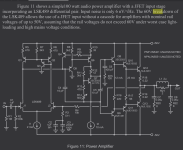
I've just come across the attached design from Bob Cordell's LSK489 Application Note where he points out just that:You may have to cascode the JFETs, because of insufficient voltage handling or because their gate current increases too much at high drain-source voltages when there is drain current flowing (I believe they blame that on impact ionization in the channel).
So from this, I assume I need to to figure out some 60V breakdown TO-236 JFETs. Are there some known recommendations for those?The 60V breakdown of the LSK489 allows the use of a JFET input without a cascode for amplifiers with nominal rail voltages of up to 50V, assuming that the rail voltages do not exceed 60V under worst case light-loading and high mains voltage conditions.
Bob utilizes a current mirror as an active load in this amp, but I guess I could get away with one load resistor (just like it's in my amp's schematic) after the supposed drop-in replacement of the BJTs with JFETs?
Sure, I'm preparing a MicroCap simulation, but the problem I've faced with is that I can't find a SPICE model for the 2SD2390\2SB1560 output darlingtons.As the transconductance will be less than that of the bipolar transistors, you will have to analyse loop gain and stability.
My current idea is to replace them with some SPICE models of darlingtons with similar hFE and fT, but it also turned out not to be so easy 🙂 Competing power darlingtons doesn't specify fT. This presumably says that it's far less than 55MHz of 2SD2390\2SB1560. The closest ones I could find so far are small signals MMBTA13\MMBTA63, though with much higher fT of 125MHz. Not sure if these ones could be a fair replacement in the simulation for purposes of the stability analysis.
Attachments
Last edited:
And how are you going to deal with the DC versus AC gain without using capacitors?
The feedback net in this circuit has unitary gain for DC and 19.5 for AC.
If you remove this cap too (J2 gate), DC gain will go to 19.5 which will complicate the offset at the output.

The feedback net in this circuit has unitary gain for DC and 19.5 for AC.
If you remove this cap too (J2 gate), DC gain will go to 19.5 which will complicate the offset at the output.
Chasing minuscule imperfections introduced by coupling capacitors while relying on passive loads seems a bit counterintuitive.Bob utilizes a current mirror as an active load in this amp, but I guess I could get away with one load resistor (just like it's in my amp's schematic) after the supposed drop-in replacement of the BJTs with JFETs?
He stated that he’s solving that by never getting any DC on the inputs.And how are you going to deal with the DC versus AC gain without using capacitors?
ron68, just to put it clear, at the current iteration of improvements, I'm eliminating the side effect of shorting the input cap only (the one that causes 0.1V DC at the speaker output).And how are you going to deal with the DC versus AC gain without using capacitors?
The feedback net in this circuit has unitary gain for DC and 19.5 for AC.
If you remove this cap too (J2 gate), DC gain will go to 19.5 which will complicate the offset at the output.
View attachment 1414150
If and when this one would be successfully resolved, after testing the improved design in the real life, and it's ready for the next small iteration, I'll be measuring the output DC with C2\C3 in place and with those shorted and making a decision on what to do next.
Meanwhile, if we'd imagine I'm facing with an inadequate level of output DC right now, I'd go for implementing the DC servo option. Mr. Nikolay Sukhov in his designs as well as Mr. Marcel van de Gevel in a post above reassured me that it's the first option to consider when we want to get some real Hi-Fi fleur 🙂
njswede, that was actually stated for the input cap only, but not for the feedback's DC unity gain cap 🙂He stated that he’s solving that by never getting any DC on the inputs.
In my case, improvements have to be done isolated and iteratively.Chasing minuscule imperfections introduced by coupling capacitors while relying on passive loads seems a bit counterintuitive.
If and when I'd successfully implement the BJTs -> JFETs replacement (and not decide to go for an opamp with a JFET input instead, for example), then the time for considering the active load may come.
Until that time, I'm concentrated on bringing the discrete JFETs input into life with some better performance than the current BJT input without that active load anyway.
Meanwhile, if we'd imagine I'm facing with an inadequate level of output DC right now, I'd go for implementing the DC servo option. Mr. Nikolay Sukhov in his designs as well as Mr. Marcel van de Gevel in a post above reassured me that it's the first option to consider when we want to get some real Hi-Fi fleur 🙂
For the record, I think bucks bunny's post #21 is essentially correct. That is, a DC servo loop is a high-pass filter, just like an AC coupling, so it also has roll-off and phase shift at low frequencies. Both for an AC coupling and for a DC servo loop, those can be kept very small by choosing a low cut-off frequency. My post #24 was just a reply to post #22, not to #21.
Nonetheless, DC servo loops and combinations of DC servo loops with AC coupling capacitors have some advantages compared to only using AC coupling capacitors. You have more freedom to place the poles and zeros where you want them, so you can for example make a second-order Butterworth high-pass transfer instead of just a cascade of first-order responses, or accept a small subsonic bump to get an unusually small phase shift at 16 Hz and above. You can make the circuit very insensitive to mismatch in the input stage. It's easier to keep the values of the capacitors low, so you can use a high-quality dielectric if you like to without the capacitors getting large and expensive.
If you want a DC servo without any phase shift or roll off, you could make a mixed-signal autocalibration loop (ADC-digital state machine-DAC) that automatically trims away the offset before turning on the output relay (assuming there is such a relay). Most would consider that overdesign, but if you think it is fun to try it, just go ahead.
It's all perfectionism, of course. Most discussions on this forum are.
the amplifier makes more distortion than the cap, so imaginary problems can be solved with imaginary solutions.
Just buy expensive caps that do imaginary things and show us actual data it does anything....good luck.
Where do people find things to waste so much time with?
When working as a mechanic, you get accused of ripping people off. But I didnt have too. They requested all kinds of unneeded repairs.
They usually ripped themselves off. It got old arguing with their imagination.
- Home
- Amplifiers
- Solid State
- Eliminating an input DC blocking cap