You’re doing it backwards. The distortion you eliminate by removing capacitors will completely drown in the distortion caused by the pretty crude amplifier design.In my case, improvements have to be done isolated and iteratively.
Address what you believe to the biggest contributor to distortion first, measure and listen, and move on to the next. That doesn’t just apply to amplifiers, but to engineering in general.

Coupling capacitors primarily cause low-frequency roll-off and phase shift. It is hard to imagine that there is anything else in the amplifier causing more low-frequency roll-off and phase shift than the coupling capacitors (or the DC servo loop, if there were one).
Regarding redesigning for JFET input devices: because of the lower transconductance, imbalance of the DC currents in the input stage may have a bigger effect on offset than with bipolar transistors. That could be a reason to update the biasing first, for example to something with a current mirror.
Regarding redesigning for JFET input devices: because of the lower transconductance, imbalance of the DC currents in the input stage may have a bigger effect on offset than with bipolar transistors. That could be a reason to update the biasing first, for example to something with a current mirror.
You've got a point that it's probably not the same type of distortion. But still. Is it even worth chasing? Here's a fairly typical input section. 0.1dB down and 8 degrees phase shift at 5Hz? Is that really worth all that effort?Coupling capacitors primarily cause low-frequency roll-off and phase shift
...and unless you're going full Kamikaze and skip all kinds of DC blocking, you're going to have a filter SOMEWHERE, and that filter WILL have roll-off and phase shift. So what have you gained?
Stop and think for a second!ron68, just to put it clear, at the current iteration of improvements, I'm eliminating the side effect of shorting the input cap only (the one that causes 0.1V DC at the speaker output).
You're NOT eliminating the effect of shorting the input capacitor. The 0.1V offset is NOT what the input capacitor is supposed to protect you against. It's supposed to protect you from DC that's accidentally introduced on the input, which can happen for a number of different reasons. If you keep the capacitor that's decoupling DC from ground in the feedback loop, you're limiting the DC gain to 0dB, but you're still passing any DC on the input straight through. If you take out that capacitor too, you're really playing Russian roulette...
You have to separate normal steady state operation from abnormal conditions!
More than once that input caps saved a few woofers as the source decided to identify itself as a battery one day. I repaired quite a few DC coupled amplifiers (then also very often without DC protection as this was supposedly introducing distortion) and loudspeakers as a consequence in the past. Often audiophile nonsense stuff with more follow up damage than necessary. I recall being a regular Velleman K4700 customer/installer 😉
Last edited:
You've got a point that it's probably not the same type of distortion. But still. Is it even worth chasing? Here's a fairly typical input section. 0.1dB down and 8 degrees phase shift at 5Hz? Is that really worth all that effort? View attachment 1414370
...and unless you're going full Kamikaze and skip all kinds of DC blocking, you're going to have a filter SOMEWHERE, and that filter WILL have roll-off and phase shift. So what have you gained?
It's all a matter of budgetting. Ideally the whole chain from microphones to loudspeakers should be flat within 0.2 dB over the audio range, but that is not going to happen, because the microphones and loudspeakers are already worse than that. The best you can do then is ensure that the circuitry in between the microphones and loudspeakers has negligible frequency response errors compared to the loudspeakers.
For harmonic distortion, people routinely design 1 ppm distortion amplifiers to drive 1 % distortion loudspeakers, so about a factor of 10000 less distortion is attributed to the amplifier than to the loudspeaker. When you do the same with frequency response errors, that -0.00876 dB and -2.5728 degrees at 16 Hz is suitable for a -87.6 dB and -25728 degrees at 16 Hz loudspeaker.
All in all, it is perfectionism, but it is not crazier than designing for very low amplifier distortion.
(Regarding my personal preference, I neither design for 1 ppm distortion nor for complete DC coupling. 0.01 % is good enough for me and I usually combine an input coupling capacitor with a servo loop to get a second-order Butterworth high-pass response at 1 Hz or so. )
I think you’re mixing apples and oranges. A very slight drop off of a fraction of a dB in the infrasonic range isn't as offensive as, say, a fairly low odd harmonic distortion.
Perfectionism often asserts the knowing of all things relevant, that in audio suggests sonically relevant as directed toward the object of perfectionism. I believe there is still much to be realized or clearly understood, particularly as related to the mechanics of hearing in relation to physical measurements and the reality.
I mostly use DC servo's when needed. Mainly because it allows for the use of high value resistors in conjunction with low value capacitors of the COG/NPO variety. These usually don't pass high frequency signals and can be applied to have little effect in some form of limited operating range, much like trimmers on op-amps.
A friend just purchased an MP1 Atma-Sphere. This contains numerous copper-foil teflon coupling capacitors. In my view the only way to compete with such devices from a purely technical perspective seems to use DC servo methods perhaps using COG/NPO's in attempting to cut down or remove their sonic impact.
If a non-cap-in-signal-path design is preferred, design such an amplifier or purchase one, and accept the unavoidable shortcomings.
If a J/mosFet-at-the input design is preferred, design such an amplifier or purchase one, and accept the unavoidable shortcomings.
If a BJT-at-the input design is preferred, design such an amplifier or purchase one, and accept the unavoidable shortcomings.
Caps are nice chaps, avoiding mishaps but aging. No rose garden/paradise entries available. Modding is not the way really.
Notice that most if not all people are unable to detect a level difference of 2dB 'at serious room performance'.
So, what to worry about, mate?
What on Earth does 'at serious room performance' mean?
During double-blind tests, levels are normally matched within 0.1 dB because there are people who hear 0.2 dB differences. The same holds for frequency responses, if the test is meant for detecting something else.
During double-blind tests, levels are normally matched within 0.1 dB because there are people who hear 0.2 dB differences. The same holds for frequency responses, if the test is meant for detecting something else.
I think you’re mixing apples and oranges. A very slight drop off of a fraction of a dB in the infrasonic range isn't as offensive as, say, a fairly low odd harmonic distortion.
As far as I know, an amplifier with no distortion and a frequency response dropping to -0.1 dB at 16 Hz sounds exactly the same as one with 0.01 % of third-order distortion and no drop at 16 Hz. In either case, the errors are too small to hear - as they should be.
Thank you, but I think you may have a wrong assumptions regarding what I'm doing or going to do. For instance, I could have no plans to do what you're describing (whole amp redesign or smth along those lines) at all.You’re doing it backwards. The distortion you eliminate by removing capacitors will completely drown in the distortion caused by the pretty crude amplifier design.
Address what you believe to the biggest contributor to distortion first, measure and listen, and move on to the next. That doesn’t just apply to amplifiers, but to engineering in general.
I've created this thread to learn, get ideas and guidance in achieving the very specific engineering goal. Everything else (including religious wars on caps vs no caps vs DC servos, what should be considered a 'good' amp or 'bad' amp design, anything) is kind of irrelevant for me. I'm concentrated on the specific engineering goal for whatever reason I might have.
Returning to it, I've described some issues in the post #31 I'm facing with and solving at the moment.
This is probably the best I could say on the matter right now.
I'm not quite understand why. Currently, the 0.1V output DC offset is created due to the Q5125 base current flowing through 56k R6405, but the Q5105 base current instead of flowing through the matching 56k R5025, flows through a much lower source output resistance. If that's true, then by using JFETs (devices with much lower gate currents), the absolute DC offset value should become lower proportional to a decrease of the current:Regarding redesigning for JFET input devices: because of the lower transconductance, imbalance of the DC currents in the input stage may have a bigger effect on offset than with bipolar transistors.
Voff_JFET = Voff_BJT * (IGate_JFET / IBase_BJT)
Isn't it the case?
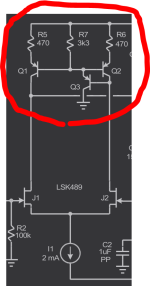
Are you talking about something like on the attached Bob Cordell's sample, correct?That could be a reason to update the biasing first, for example to something with a current mirror.
Attachments
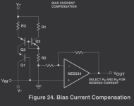
Or did you mean something similar to this one? Just learned it from OnSemi's Audio Circuits Using the NE5532/4 🙂Regarding redesigning for JFET input devices: because of the lower transconductance, imbalance of the DC currents in the input stage may have a bigger effect on offset than with bipolar transistors. That could be a reason to update the biasing first, for example to something with a current mirror.
Attachments
I'm not quite understand why. Currently, the 0.1V output DC offset is created due to the Q5125 base current flowing through 56k R6405, but the Q5105 base current instead of flowing through the matching 56k R5025, flows through a much lower source output resistance. If that's true, then by using JFETs (devices with much lower gate currents), the absolute DC offset value should become lower proportional to a decrease of the current:
Voff_JFET = Voff_BJT * (IGate_JFET / IBase_BJT)
Isn't it the case?
There are several effects contributing to the offset, such as:
Base current and unequal resistances. This will indeed be essentially gone with JFETs.
Base current mismatch due to unequal hFEs. Also gone with JFETs and not dominant anyway because of the different resistances.
Base-emitter or gate-source voltage mismatch at a given collector or drain current. You are going to select your FETs to get this under control.
Differences between the collector or drain currents that flow through the input transistors, as set by the rest of the amplifier circuit. You can calculate this back to an equivalent input offset voltage by dividing by the input stage transconductance (and to an equivalent input offset current by dividing by the input stage current gain, but that goes to near zero again with JFETs).
This differences-between-drain-currents-calculated-back-to-an-offset-voltage term might get worse with JFETs. Then again, I don't know if it gets big enough to be a problem. Looking at the schematic, it is clear that the designers did their best to keep the currents well-balanced.
Are you talking about something like on the attached Bob Cordell's sample, correct?
Yes, but I don't know if it is needed. A current mirror in the signal path also complicates the high-frequency behaviour, so I rather avoid them if they are not required.
1st, let's rule out the DC servo. The caps in the servo are also in the signal path. Thus, this is not the solution.
2nd, the DC blocking cap in the feedback network is also in the signal path. If you care the cap at the input, you should also care the cap in the feedback network.
Let's say you short all the coupling caps in the signal path. The only way to address DC offset is through a pot. Add a pot to long tail pair input stage as below.

The drawback is you need to adjust the DC offset every time you switch between the input sources. Each source might have different DC offset at the output.
2nd, the DC blocking cap in the feedback network is also in the signal path. If you care the cap at the input, you should also care the cap in the feedback network.
Let's say you short all the coupling caps in the signal path. The only way to address DC offset is through a pot. Add a pot to long tail pair input stage as below.
The drawback is you need to adjust the DC offset every time you switch between the input sources. Each source might have different DC offset at the output.
- Home
- Amplifiers
- Solid State
- Eliminating an input DC blocking cap