Thank you, that manual is different than the one I have. Still doesn't tell me what voltage I should read on the white wire though.
Yes, I was expecting kv dc voltage on the white wire, I think the problem is in the bias block, but I'm not good with formal repair (reading schematics, testing individual components, etc).
I'll pull it apart today and see what I can find.
Yes, I was expecting kv dc voltage on the white wire, I think the problem is in the bias block, but I'm not good with formal repair (reading schematics, testing individual components, etc).
I'll pull it apart today and see what I can find.
With both tweeters not working, the most likely cause is deterioration of conductive coating on the diaphragm or contact between conductive coating and HV supply terminal. Often you can verify this by exhaling moist air from your lungs onto the diaphragm while playing music and see if they spring to life momentarily. Be sure to try exhaling on both sides of the diaphragm because usually the coating is only on one side.Symptom - both tweeters not working
Not sure how much it will help, but since you are new to ESLs here is a Japanese website with some pics of diaphragm repair.
SA-S1 Repair(kei's page)
Wow, you are a brave man hooking up a regular tweeter to the output of a step-up transformer meant to drive an ESL. You could easily have destroyed the driving amplifier by asking it to drive a short, or blown the tweeter from sending 100s(1000s?) of volts into. Or, perhaps you noticed that SONY had put two 15K resistors in series between the step-up transformer and ESL terminals(CN4 & CN5). When you connected up your regular tweeter, almost all the voltage was dropped across the 15K resistors and the amplifier was only asked to drive about an 8 ohm load(assuming step-up ratio of transformer is 60:1 which is fairly common). In any case, be careful handling those black and red wires. They could easily have as much as 1000Vrms on them at fairly substantial current.When I hook regular tweeter to the black and red I get sound but very quiet - louder than the esl tweeter but not nearly loud enough. When I hook up a piezo horn tweeter to black and red the piezo is very loud, maybe too loud to balance with the woofer.
>> You may want to measure the DC resistance between the red and black wires to confirm it is still in the 30K range and you didn't damage one of the internal 15K resistors.
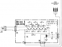
Looking at the schematic, the bias voltage is likely in the 2kV to 3kV range. If you measure the AC input voltage between the pins of CN1 we can calculate exactly what the HV output should be.Schematic (from post 2, same as in the service manual) shows voltages of 1kv and 6kv in the bias block connected through transformer to the tweeter but I don't know what voltages I am supposed to read on the wires themselves…I read about 15 mV on the white wire, from my limited esl knowledge I thought it should be hundreds if not a thousand or so volts on the diaphragm…. give me some ballpark idea of what dc voltage should be on the white wire supplying the diaphragm bias, as I suspect that is the problem at this point.
HVdc = 7 x sqrt(2) x Vrms(CN1)
When you measured the 15mV on the white wire, what were you referencing it to? (ie what was the other terminal of your meter connected to. Do you have a HV probe?
The proper way to measure the HV would be between the white wire(terminal CN3) and either the black or red wires(CN4 or CN5). Notice that there is a 100Mohm resistor in series between the HV multiplier and the HV terminal CN3. So, if you use a DVM with input impedance of 10Mohm, you are forming a 10:1 voltage divider, so 3kVdc would show up as 300Vdc. In actuality, it will likely be much less because the HV multiplier is not made to handle the current draw from a 110Mohm load. But, you should certainly be able to get > 100Vdc and similar magnitude AC ripple. I’m fairly confident you will find the supply is working fine, and the problem is in the diaphragm coating or contact, as mentioned at the beginning of this post.
Attachments
Last edited:
With both tweeters not working, the most likely cause is deterioration of conductive coating on the diaphragm or contact between conductive coating and HV supply terminal. Often you can verify this by exhaling moist air from your lungs onto the diaphragm while playing music and see if they spring to life momentarily. Be sure to try exhaling on both sides of the diaphragm because usually the coating is only on one side.
Not sure how much it will help, but since you are new to ESLs here is a Japanese website with some pics of diaphragm repair.
SA-S1 Repair(kei's page)
Thanks. I watched a youtube video on cleaning the esl tweeters, it was quite helpful. It was a very detailed disassembly and cleaning and reassembly. I haven't cleaned them yet but I might get into that in the next couple of days.
Wow, you are a brave man hooking up a regular tweeter to the output of a step-up transformer meant to drive an ESL. You could easily have destroyed the driving amplifier by asking it to drive a short, or blown the tweeter from sending 100s(1000s?) of volts into. Or, perhaps you noticed that SONY had put two 15K resistors in series between the step-up transformer and ESL terminals(CN4 & CN5). When you connected up your regular tweeter, almost all the voltage was dropped across the 15K resistors and the amplifier was only asked to drive about an 8 ohm load(assuming step-up ratio of transformer is 60:1 which is fairly common). In any case, be careful handling those black and red wires. They could easily have as much as 1000Vrms on them at fairly substantial current.
Not brave at all. I measured the ac voltage across the red and black wires prior to hooking anything up. At moderate volume the ac voltage was around 14 - 35 V. At first I hooked up an old crappy car audio 6x9 so if it blew it wouldn't be a painful loss. It had very low spl output. Next I tried a cheap tweeter, also very low output. Just for fun I hooked up the cheap piezo horn tweeter, and finally I got some decent spl.
Looking at the schematic, the bias voltage is likely in the 2kV to 3kV range. If you measure the AC voltage between the pins of CN1 we can calculate exactly what the HV output should be.
HVdc = 7 x sqrt(2) x Vrms(CN1)
When you measured the 15mV on the white wire, what were you referencing it to? (ie what was the other terminal of your meter connected to. Do you have a HV probe?
One terminal on the white wire, the other on metal electronics housing, which I assume is ground (it didn't kill me when I touched it so it should be ground).
I do not have a HV probe, I just have a crappy $5 DMM with a 200 and 750 VAC setting. The highest dc range is 1000 VDC.
I'm assuming I should be measuring AC on the red and black wires and DC on the white wire.
The proper way to measure the HV would be between the white wire(terminal CN3) and either the black or red wires(CN4 or CN5). Notice that there is a 100Mohm resistor in series between the HV multiplier and the HV terminal CN3. So, if you use a DVM with input impedance of 10Mohm, you are forming a 10:1 voltage divider, so 3kVdc would show up as 300Vdc. In actuality, it will likely be much less because the HV multiplier is not made to handle the current draw from a 110Mohm load. But, you should certainly be able to get > 100Vdc and similar magnitude AC ripple. I’m fairly confident you will find the supply is working fine, and the problem is in the diaphragm coating or contact, as mentioned at the beginning of this post.
I will get you a reading of the black (and red) wire referenced to the white wire posthaste. I already did this last night and the readings were very low, IIRC somewhere in the neighbourhood of almost 0 VDC and a few (less than 20) VAC. But I don't remember exactly so I'll do it again.
I do remember that I never got anywhere close to 100 V (DC or AC) anywhere I checked. I didn't read any higher than low 30's voltage AC on any of the wires (referenced to any of the other wires or ground) and not even close to 1 VDC anywhere. IIRC.
I'll do it all again and give exact meter readings with an hour or two.
Thanks very much for the help, it is much appreciated.
Also (and I'm not sure if this helps or not) sometimes with only one wire connected I would get sound from the regular tweeters (red or black wire), but very quiet and only sometimes which I found incredibly odd. Also sometimes I got a mild shock when touching ground when one of the red or black wires was hooked to the tweeter, but again this was only every once in awhile. And the shock was very mild, nothing close to a 110 VAC shock.
First test completed. This is probably the easiest and most telling test.
While listening to the esl tweeter (it has to be close to my ear to hear anything, like 1 cm from my ear), I disconnect the white wire and there is NO DIFFERENCE AT ALL in the sound coming from the tweeter.
I tried connecting and disconnecting it several times and there no difference at all in the sound with the white wire connected or disconnected.
As I said, there's basically no voltage at all (15 mV) on the white wire, the white wire literally doesn't seem to be doing anything at all.
Next up - voltage readings on the red, white and black wires. I'll have that info soon.
PS - exhaling on the diaphragm has no effect at all. I exhaled enough to get dizzy and it did nothing. I'm not blowing hard, just gently exhaling.
Yeah, doesn't look like there is any connection between the electronics housing(gnd) and the HV module....One terminal on the white wire, the other on metal electronics housing, which I assume is ground (it didn't kill me when I touched it so it should be ground).
Hmmmm...do you know what the input impedance is?I do not have a HV probe, I just have a crappy $5 DMM with a 200 and 750 VAC setting. The highest dc range is 1000 VDC.
If not the usual 10Meg, it could be messing with your readings from loading down the high impedance ESL circuit.
Yes. If you input 2kHz tone and measure the input to the transformer input(CN2 pins) and set volume for 1Vrms. Then measure AC voltage between red and black wires. Should be in the 50Vrms - 100Vrms range. This will let you know what the step-up ratio of the transformer is. You probably are aware that many cheap DMMs measure well below actual Vrms as frequency increases, but the ratio will still be valid. Also, since this uses an active crossover, there may not be much drive signal to the ESL < 2kHz.I'm assuming I should be measuring AC on the red and black wires and DC on the white wire.
Voltage readings - spl level is low, woofer is playing at or a bit below normal speaking voice spl and readings are taken with no tweeter load attached. A music track is playing.
Red and black wires - there's 2 - 12 VAC fluctuating up and down with the music signal. There's 0 VDC as expected, it would be bad if there was dc on these wires I think.
Red and white wires - there's 11.6 VAC with meter terminals on the red and white wires. It's pretty steady at 11.6 but sometimes it fluctuates between 11.5 and 11.6 VAC. There's also 11.6 VDC with the leads on the red and white wires.
Black and white wires - exactly the same result as when the leads are on the red and white wires.
White wire and metal speaker housing - I assume this metal housing inside the speaker is ground. When leads are on the white wire and the metal housing voltage is constantly jumping around between about 8 mV and 13 mV DC. (It starts out much higher with peaks up to 30 mV DC but after a few seconds it calms down and peaks around 13 mV DC. There's 0 VAC with leads on the white wire and metal housing.
To get measurement at the other end of the wires (on the bias board) and at CN points as requested will require a more complete disassembly and I'm not sure if it's warranted. Parts on the bias board do not seem to be user replaceable - from what little I can see it looks like the entire board is coated in something like a thick epoxy. To replace components I would have to first excavate them out of the epoxy coating.
Based on this and your exhale test, problem is either the HV power supply or the diaphragm contact...I disconnect the white wire and there is NO DIFFERENCE AT ALL in the sound coming from the tweeter.
Ha! been there done that. 😀...exhaling on the diaphragm has no effect at all. I exhaled enough to get dizzy and it did nothing. I'm not blowing hard, just gently exhaling.
So probably not the coating unless it has completely deteriorated , but still could be the contact which was the problem identified on the Japanese website.
Shock like a momentary static discharge? or a continuous buzz....sometimes I got a mild shock when touching ground when one of the red or black wires was hooked to the tweeter, but again this was only every once in awhile.
I keep forgetting that these use active crossover, so there is not that much signal getting to them with most music.
Another easy test for the HV supply is to dim the lights, and with no music playing slowly bring the white wire in contact with the red or black wire. If HV is working, you should see a very small momentary blue spark just before contact.
Yeah, doesn't look like there is any connection between the electronics housing(gnd) and the HV module.
Hmmmm...do you know what the input impedance is?
If not the usual 10Meg, it could be messing with your readings from loading down the high impedance ESL circuit.
Yes. If you input 2kHz tone and measure the input to the transformer input(CN2 pins) and set volume for 1Vrms. Then measure AC voltage between red and black wires. Should be in the 50Vrms - 100Vrms range. This will let you know what the step-up ratio of the transformer is. You probably are aware that many cheap DMMs measure well below actual Vrms as frequency increases, but the ratio will still be valid. Also, since this uses an active crossover, there may not be much drive signal to the ESL < 2kHz.
Thanks. As noted it's going to be tougher getting measurements off the bias board CN points. I can but...
Isn't it significant that there's no difference at all in sound from the esl tweeter whether the white wire is connected at all?
IMO this leads to the fact that the bias board is not working at all. Admittedly I don't know much about component level troubleshooting but shouldn't there be a very dramatic decrease in spl level if you disconnect the white wire?
Based on this and your exhale test, problem is either the HV power supply or the diaphragm contact.
Ha! been there done that. 😀
So probably not the coating unless it has completely deteriorated , but still could be the contact which was the problem identified on the Japanese website.
Shock like a momentary static discharge? or a continuous buzz.
I keep forgetting that these use active crossover, so there is not that much signal getting to them with most music.
Another easy test for the HV supply is to dim the lights, and with no music playing slowly bring the white wire in contact with the red or black wire. If HV is working, you should see a very small momentary blue spark just before contact.
I posted while you were typing...
I don't know if the shock was momentary on continuous. I move pretty quick when I get a shock. I assume it would have been continuous if I held onto it.
I have seen spark when connecting the white wire but can't remember what I was connecting it to at the time - it would have been the meter leads to either the other colored wires or the metal housing.
I'll take the tweeters apart later today or tomorrow and clean them and take a look at the contacts in that area.
Based on this and your exhale test, problem is either the HV power supply ....
The HV power supply is the bias board, correct?
These AC & DC readings were taken with no music playing?...Red and white wires - there's 11.6 VAC with meter terminals on the red and white wires. It's pretty steady at 11.6 but sometimes it fluctuates between 11.5 and 11.6 VAC. There's also 11.6 VDC with the leads on the red and white wires.
If you can tell me your DMM input impedance I can stick it in an LTspice SIM I have to see if readings seem reasonable or not.
That sucks 🙁... looks like the entire board is coated in something like a thick epoxy. To replace components I would have to first excavate them out of the epoxy coating.
This appears to be my DMM, same part number and it looks the same. I don't know anything about it other than it's cheap crap that usually does what I need (usually 12 VDC measurements).
These AC & DC readings were taken with no music playing?
If you can tell me your DMM input impedance I can stick it in an LTspice SIM I have to see if readings seem reasonable or not.
That sucks 🙁
All the voltage readings were taken with music playing at low spl and without the tweeter connected. I was taking the voltage readings off the wire where it connects to the tweeter wires but without the tweeter connected.
OK, if you've seen sparks then the HV supply is most likely working just fine and your plan to check the contact area is most logical next step....I have seen spark when connecting the white wire but can't remember what I was connecting it to at the time - it would have been the meter leads to either the other colored wires or the metal housing.
BTW, if you happen to have access to an old JansZen or RTR panel it would provide a good test of the HV supply and driving electronics.
Yes, The HV power supply is the diode/capacitor ladder shown in the "bias block" portion of the schematic.The HV power supply is the bias board, correct?
With no music playing I get 11.3 VAC and 11.3 VDC with the leads on the white and red wires. Pretty close to the same thing I got with music playing, about 0.2 V less when I stop the music playback or disconnect the rca input.
Your readings seem reasonable if the input impedance of your DMM was 1Meg.With no music playing I get 11.3 VAC and 11.3 VDC with the leads on the white and red wires. Pretty close to the same thing I got with music playing, about 0.2 V less when I stop the music playback or disconnect the rca input.
BTW, was there supposed to be link to your DMM in post#33?
Bingo!
So your 11.3 Vdc reading means the HV supply was putting out an average 1.1kVdc while driving the 101Mohm load.
With only the ESL hooked up, it would bias the diaphragm to about 2.5kVdc.
So your 11.3 Vdc reading means the HV supply was putting out an average 1.1kVdc while driving the 101Mohm load.
With only the ESL hooked up, it would bias the diaphragm to about 2.5kVdc.
Attachments

Last edited:
- Home
- Loudspeakers
- Planars & Exotics
- electrostatic tweeter repair Sony SA-EX100