Has anyone tried using an electrostatic speaker as a microphone? There are many parallels between the two in function; however, while the unimpeded exposure of the diaphragm condenser mic is great, the inherent asymmetry requires extremely close tolerances in construction.
I don't have an electrostatic speaker handy, but for the sake of science, would anyone mind connecting a scope to the output of theirs and seeing if some sine waves could be reproduced?
I don't have an electrostatic speaker handy, but for the sake of science, would anyone mind connecting a scope to the output of theirs and seeing if some sine waves could be reproduced?
Spasticteapot,
Theoretically all speakers would be capable of an electrical output that could be used as a microphone. What it would sound like is another story but they will all function this way. Moving a diaphragm that has a coil attached in a magnetic field will produce an electrical signal. Many cheap speakers have been used this way but not typically for high fidelity audio.
Theoretically all speakers would be capable of an electrical output that could be used as a microphone. What it would sound like is another story but they will all function this way. Moving a diaphragm that has a coil attached in a magnetic field will produce an electrical signal. Many cheap speakers have been used this way but not typically for high fidelity audio.
Has anyone tried using an electrostatic speaker as a microphone? There are many parallels between the two in function; however, while the unimpeded exposure of the diaphragm condenser mic is great, the inherent asymmetry requires extremely close tolerances in construction.
Push-pull dipole ESLs make great microphones: low distortion and flat response.
You will need a high impedance low noise pre-amp.
HF bandwidth is limited by diaphragm mass, you will need to use 3.5uM or thinner or plan to fix with EQ.
LF bandwidth is limited by fundamental diaphragm resonance. This is tricky as you need to get resonance very low < 20Hz using very light tension, yet enough tension to avoid diaphragm instability. Also, you will need to damp the resonance with a thin acoustic mesh applied to the stators.
Single ended ESL pressure microphones (like B&K measurement mics) are a completely difference animal.
Flat response is only had below resonance, so you have to use a very thin small diaphragm that you can apply high tension to.
Of course, a large planar ESL would make a very directional mic, as off-axis high frequencies would cancel; again the speaker model running in reverse.
No, don't try to use your ribbon mic as a speaker, it doesn't get very loud LOL. But if anyone ever wanted to bug my house, they could certainly just tap into the wires to my newform ribbons (actually line-shaped monopolar planar dynamics). At least until I turn the stereo on.
No, don't try to use your ribbon mic as a speaker, it doesn't get very loud LOL. But if anyone ever wanted to bug my house, they could certainly just tap into the wires to my newform ribbons (actually line-shaped monopolar planar dynamics). At least until I turn the stereo on.
I'd imagine my electrostatic headphones could make acceptable mics with the right power supply and preamp.
Because of reciprocity of transducers it is possible to use electrostatic speaker as a microphone. In fact, there are some fig8 dual stator capsules with very similar construction (but of course, way scaled down), so in principle you should be able to hear "at least something". However, because of difference in implementation (after all, in a microphone we do not emit, but receive the signal) the speaker would not be optimized for critical music recording and practicality of such "microphone" would be very questionable.
In any microphone besides low distortions we are interested in a few things: frequency response, polar pattern, noise, good transient response, lack of resonances (or IOW, well controlled). Neither of those can be achieved in such a big transducer as a speaker.
The frequency response--while probably that would be perfectly possible to get a more or less usable bottom end, since this is a dipole (fig8) mainly mass controlled system the top end will be limited mainly by the microphone/speaker width. Say, if it is 12" then we will be lucky to get the top response up to some 800Hz (!!!) on a good day.
Considering there is no top end, the polar pattern in our case won't make any sense, other than it is symmetrical fig8, with good 90* rejection. Really, for a good and usable polar pattern we need a small capsule.
Noise most likely won't be optimized, either. Unlike speakers, in microphones there is no need for such a HUGE spacing between diaphragm and stators. In most of condenser microphone it is some 12-25um for maximum efficiency, with bias voltage at some 40-200V, depending on a mic. In a speaker the area is much larger, so it is good, but the distance is so much bigger that I suspect it is not an equal tradeoff. You can easily scale things up--I am too lazy to make calculations...
The main problem in fact, might be very complex resonant modes, which are completely undamped by the loading air, leading to very poor transient and frequency responses, besides high distortions. You will need to add some damping (say to put felt screens right in front and on the back), but then it will create all kind of different problems.
We could also create an enclosed volume, with a certain air compliance (which BTW, would help with top frequency response), however, since we have a mass controlled system in order to get flat response we will also need to create an infinite volume (in practice, that would be something like tapered and stuffed labyrinth of considerable length). That would be quite a complication, which is hardly worth an effort considering all other things...
(True) ribbon speaker should be more successful as a microphone, but still the top end response will be very limited and undamped resonances too big of a factor to be able to talk about some kind of sound quality...
Hope this is of help.
Best, M
In any microphone besides low distortions we are interested in a few things: frequency response, polar pattern, noise, good transient response, lack of resonances (or IOW, well controlled). Neither of those can be achieved in such a big transducer as a speaker.
The frequency response--while probably that would be perfectly possible to get a more or less usable bottom end, since this is a dipole (fig8) mainly mass controlled system the top end will be limited mainly by the microphone/speaker width. Say, if it is 12" then we will be lucky to get the top response up to some 800Hz (!!!) on a good day.
Considering there is no top end, the polar pattern in our case won't make any sense, other than it is symmetrical fig8, with good 90* rejection. Really, for a good and usable polar pattern we need a small capsule.
Noise most likely won't be optimized, either. Unlike speakers, in microphones there is no need for such a HUGE spacing between diaphragm and stators. In most of condenser microphone it is some 12-25um for maximum efficiency, with bias voltage at some 40-200V, depending on a mic. In a speaker the area is much larger, so it is good, but the distance is so much bigger that I suspect it is not an equal tradeoff. You can easily scale things up--I am too lazy to make calculations...
The main problem in fact, might be very complex resonant modes, which are completely undamped by the loading air, leading to very poor transient and frequency responses, besides high distortions. You will need to add some damping (say to put felt screens right in front and on the back), but then it will create all kind of different problems.
We could also create an enclosed volume, with a certain air compliance (which BTW, would help with top frequency response), however, since we have a mass controlled system in order to get flat response we will also need to create an infinite volume (in practice, that would be something like tapered and stuffed labyrinth of considerable length). That would be quite a complication, which is hardly worth an effort considering all other things...
No, don't try to use your ribbon mic as a speaker, it doesn't get very loud LOL. But if anyone ever wanted to bug my house, they could certainly just tap into the wires to my newform ribbons (actually line-shaped monopolar planar dynamics). At least until I turn the stereo on.
(True) ribbon speaker should be more successful as a microphone, but still the top end response will be very limited and undamped resonances too big of a factor to be able to talk about some kind of sound quality...
Hope this is of help.
Best, M
Last edited:
Hi,
I think large surface of an ESL should have an interesting property in a way it treats interaction with the room. It is no longer a point target like a small mic or a single ear. So there should be a considerable averaging in frequency response over area IMO as it would capture the sound like lots and lots of multiple mics. Transient response should be rather strange. This does not correspond well to what we are used to in hear from small microphones, but perhaps could have use in some applications?
Regards,
Lukas.
Government agencies do spy on people by listening through the vibration of walls from exterior to a building, there are many ways that a flat panel would have similar properties as a microphone but the equalization of the sound field would be the problem more than likely. A ribbon speaker and ribbon mic follow very similar construction methods, size and mass is the dominant difference here.
This does not correspond well to what we are used to in hear from small microphones, but perhaps could have use in some applications?
From top of my head the only application I could think of would be something like kick drum, where many engineers use large woofers as microphones. Still the size of usual wide band ESL will be too large and we get into the bleeding problems. Something like smaller ESL tweeter would be a better match here.
Government agencies do spy on people by listening through the vibration of walls from exterior to a building, there are many ways that a flat panel would have similar properties as a microphone but the equalization of the sound field would be the problem more than likely.
This is my understanding they use windows (not the walls), with laser sensing the vibrations. The major difference with ESL panel is the window glass is very stiff, and works into enclosed volume, so the entire system is stiffness controlled and the overall frequency response will be quite flat and wide (at least for the purpose of intelligibility of recorded speech). Most likely, there is even no need for EQ.
Best, M
The major difference with ESL panel is the window glass is very stiff, and works into enclosed volume, so the entire system is stiffness controlled and the overall frequency response will be quite flat and wide (at least for the purpose of intelligibility of recorded speech). Most likely, there is even no need for EQ.
Best, M
Hi,
I do not think so. The glass has a very considerable mass. So most of high or even mid range content will be just reflected back instead of setting glass into motion. Also the motion of glass should be very small and perhaps there are some limitation in laser measurement equipment as well. As I understand laser measurement system accuracy is fundamentally limited by laser's wavelength. And movement of glass is perhaps in the order of fraction of a micron which could be similar to wavelength of a laser.
Regards,
Lukas.
Hi,
I do not think so. The glass has a very considerable mass. So most of high or even mid range content will be just reflected back instead of setting glass into motion. Also the motion of glass should be very small and perhaps there are some limitation in laser measurement equipment as well. As I understand laser measurement system accuracy is fundamentally limited by laser's wavelength. And movement of glass is perhaps in the order of fraction of a micron which could be similar to wavelength of a laser.
The omni pressure operation is much less concerned with mass, but rather with stiffness. For example, one of the early Altec pressure mics had a diaphragm out of 50um glass and had 20KHz bandwidth on top. No pressure gradient or velocity transducers could do that with such diaphragm. Think of pressure operation as a barometer.
The diaphragm movement in the omni pressure mics is minimal, as well, and is limited to some sub-micron distances. I am not familiar how the laser sensors work.
In the ESL the top end is limited mostly by the length of the front-to-back signal path.
Best, M
The omni pressure operation is much less concerned with mass, but rather with stiffness. For example, one of the early Altec pressure mics had a diaphragm out of 50um glass and had 20KHz bandwidth on top. No pressure gradient or velocity transducers could do that with such diaphragm. Think of pressure operation as a barometer.
The diaphragm movement in the omni pressure mics is minimal, as well, and is limited to some sub-micron distances. I am not familiar how the laser sensors work.
Best, M
Hi,
I think there must be a significant difference between a small microphone and large area like a window glass. Pressure-like behavior can only be expected when wavelength is large compared to active area of the diaphragm(this case it is glass). When this frequency is exceeded the membrane or window glass will be receiving the pressure gradient not in phase across its area so it can not be said to be operating in "pressure" mode anymore. I could see no reason why a high or even mid range content could reach area as large as window glass in-phase with typical sound sources.
Also a 50u glass is quite not a match to a typical window glass which is 3-5mm thich(thats about 100 times more).
In the ESL the top end is limited mostly by the length of the front-to-back signal path.
Could you clarify more because as far as I know in case of ESLs the top end is limited by driving mass
Regards,
Lukas.
I would agree that the mass would limit the top end output and the front to back distance will limit the low frequency response unless the back was closed.
I would agree that the mass would limit the top end output and the front to back distance will limit the low frequency response unless the back was closed.
Dipole ESL microphone:
The front to back distance does NOT matter as far as the low frequency response is concerned. The reason this is so is because the ESL diaphragm is just responding to the acoustic sound field it is placed in. As long as the diaphragm can be approximated as lacking in stiffness and mass, the diaphragm motion will follow the air motion in the sound field exactly, and the voltage output will be directly proportional to air displacement in the sound field at all frequencies. This is distinctly different from the far-field response of the same ESL used as a speaker if constant voltage was applied to it's stators which DOES depend on the front to back distance.
The "lacking in stiffness and mass" approximation breaks down at the frequency extremes.
- the top end bandwidth is limited by the diaphragm mass.
- the low end bandwidth is limited by the diaphragm stiffness which resulting in the diaphragm resonance. For extended low end response you need very low tension to get resonance < 20Hz.
Pressure ESL microphone:
Unlike the dipole ESL microphone the top end bandwidth of the pressure ESL microphone is defined by the fundamental resonance. As such, the pressure microphone operates in the stiffness dominated regime. Voltage output is directly proportional to applied acoustic pressure and is uniform for all frequencies below the diaphragm resonance. The B&K measurement microphones mentioned in Post #3 use a metal diaphragm and very high tension to place the resonance >40kHz.
@ Bazukaz,
Very interesting idea using a large ESL to capture average sound field.
This might be useful for avoiding response variations from room modes at LF.
I may have to give it a try. All my dipole ESL microphones have been smaller than 3" x 3"(7.5cm x 7.5cm).
Hi,
I think there must be a significant difference between a small microphone and large area like a window glass. Pressure-like behavior can only be expected when wavelength is large compared to active area of the diaphragm(this case it is glass). When this frequency is exceeded the membrane or window glass will be receiving the pressure gradient not in phase across its area so it can not be said to be operating in "pressure" mode anymore.
Sorry, there is no "pressure-like" behavior, as there is no "pressure gradient" component in the stiffness controlled system, to start with. It is strictly pressure operation, with all consequences. For further details I'd suggest to consult AIP Handbook of Condenser Microphones: Theory, Calibration and Measurements.
The B&K measurement microphones mentioned in Post #3 use a metal diaphragm and very high tension to place the resonance >40kHz.
Really depends on the model of the capsule. Generally, even in B&K/Gefell measuring capsules because of (inevitable) acoustical resistance component the frequency response is quite a bit higher than tuning resonance.
Could you clarify more because as far as I know in case of ESLs the top end is limited by driving mass
Dipole ESL microphone:
- the top end bandwidth is limited by the diaphragm mass.
Against our intuition this is not the case. Here is a part of my reply to a similar question I wrote awhile ago on another forum. While that one was written in regards to ribbon microphones, because of dipole operation the principle remains still the same:
...where is the flat response in ribbons coming from?
In the "native" fig8 pattern the sound wave strikes the front of the diaphragm and creates acoustic pressure p1. Since the back of the ribbon is exposed, the same sound wave flows around the ribbon and pole pieces/magnet structure some distance (called acoustic path d) and creates some acoustical pressure p2 at the back of the ribbon. This results in pressure difference p1-p2, which in fact, is a driving force to move the ribbon.
For example, why there is a null at the 90 degrees polar response? Because the sound wave reaches both, front and back at the same time, so there is no pressure difference.
The interesting feature of this driving force is that it doubles with every octave, so the acoustical response of the ribbon actually RAISES with 6db8 rate. Now, remember that the mass controlled system naturally has a falling response? When we combine those two, that gives us an overall flat response.
Now let's see what's going on on the extremes of the bandwidth.
1) Low end:
Obviously, the tuning frequency of the ribbon would determine the lowest response. However, in the real system there always will be a slit between the ribbon itself and magnet/pole, so because of the viscosity of the air in that slit below some certain point the system turns into the STIFFNESS controlled one (the one, which defines true omni operation) and the response below that point rapidly falls--that's why it is not practical to tune the ribbon much lower that point.
2) Top end:
As we talked earlier, there is a distance d, which represents the path between front and back and obviously this distance can be translated into the wavelength.
As we talked, the driving force p1-p2 increases with each octave, but only to the point where the d represents 1/2 wavelength, because when the d reaches the full wavelength our driving force p1-p2 becomes ZERO. That is, in the condition when the wavelength of the signal becomes equal to the distance of the acoustic path d obviously the p2 will become equal to p1 (because it is 360 degree shift) and the ribbon won't be moving.
That's why if we know the acoustical path d and ribbon dimensions, it is very easy to calculate the top frequency response.
It is important to notice, the top response will also be somewhat affected by diffractions caused by magnet system cavity, but there are special graphs, which help to correct the calculations to the very high degree of accuracy.
Hopefully it helps and puts more light on how the ribbon microphones work.
Best, Mark Fouxman
Samar Audio & Microphone Design
Last edited:
Very interesting idea using a large ESL to capture average sound field.
This might be useful for avoiding response variations from room modes at LF.
Clearly, there is something I am missing here--perhaps this is a matter of semantics... What is that "average sound field" and what its significance in respect to the recorded sound source? What "response variations" are in question, considering at LF the sound source is non-directional? In the wavelengths of LF what difference it ultimately makes--large transducer, small transducer? Just cannot grasp what you mean. Care to elaborate?
Best, M
Interesting debate.
This leads to something that has puzzled me for 50 years: where are the electret speakers?
Ben
This leads to something that has puzzled me for 50 years: where are the electret speakers?
Ben
Sorry, there is no "pressure-like" behavior, as there is no "pressure gradient" component in the stiffness controlled system, to start with. It is strictly pressure operation, with all consequences. For further details I'd suggest to consult AIP Handbook of Condenser Microphones: Theory, Calibration and Measurements.
Pressure gradient is difference in pressure, so how can we say "there is no pressure gradient" when there is sound in air??
When wavelength is small compared to glass size(which is true for all but the lowest frequency) different parts of glass will be hit at different times from typical sound sources so phase is not the same across the area.
I do not really get what do you mean by "strictly pressure operation" under these conditions ?
Also at 20 kHz 4-5 mm thick glass looks like a very hard wall with thickness equal to about a quarter the wave length(compare this to ~1.7meter@50Hz).
I think in this case we must consider the medium(glass) into equation as well with its mass, stiffness etc.
Also can we assume glass will be operating in stiffness mode across the entire frequency range? I have tried to bounce a glass of the door and it seems to resonate somewhere in the low midrange.
...where is the flat response in ribbons coming from?
In the "native" fig8 pattern the sound wave strikes the front of the diaphragm and creates acoustic pressure p1. Since the back of the ribbon is exposed, the same sound wave flows around the ribbon and pole pieces/magnet structure some distance (called acoustic path d) and creates some acoustical pressure p2 at the back of the ribbon. This results in pressure difference p1-p2, which in fact, is a driving force to move the ribbon.
My experiments with ESLs(speakers, not microphones 🙂 ) showed that if membrane thickness is more than about 8-10 microns top end will be dropping.
So perhaps the same model cannot be applied to both ribbons and ESLs or it cannot be "reversed".
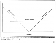
Also in the paper "Wide-range electrostatic loudspeaker" by Walker there is an interesting graph showing effects of stiffness, mass and radiation resistance vs frequency although no actual values.
2) Top end:
As we talked earlier, there is a distance d, which represents the path between front and back and obviously this distance can be translated into the wavelength.
As we talked, the driving force p1-p2 increases with each octave, but only to the point where the d represents 1/2 wavelength, because when the d reaches the full wavelength our driving force p1-p2 becomes ZERO. That is, in the condition when the wavelength of the signal becomes equal to the distance of the acoustic path d obviously the p2 will become equal to p1 (because it is 360 degree shift) and the ribbon won't be moving.
Well we must also consider the fact an ESL diaphragm is almost completely transparent to sound, at least in mid and treble where membrane stiffness can be ignored altogether. So it's motion would simply follow motion of air??
So it should not be uniform across the area, causing induced voltage to cancel out and drop with increasing frequency.
Regards,
Lukas.
Attachments
Against our intuition this is not the case. Here is a part of my reply to a similar question I wrote awhile ago on another forum. While that one was written in regards to ribbon microphones, because of dipole operation the principle remains still the same:
....
2) Top end:
As we talked earlier, there is a distance d, which represents the path between front and back and obviously this distance can be translated into the wavelength.
As we talked, the driving force p1-p2 increases with each octave, but only to the point where the d represents 1/2 wavelength, because when the d reaches the full wavelength our driving force p1-p2 becomes ZERO. That is, in the condition when the wavelength of
Hello Marik,
Thanks for sharing your knowledge on ribbon microphones. I have no experience with them, but your description of the path length limitation makes sense. I have experimented with using small ESLs (1"x1" up to 3"x3") as microphones and the top end roll off was the same for all sizes if the diaphragm thickness and % open area of the stators was the same. Perhaps the reason for the difference in behavior is that the ribbon is mass controlled so the sound wave takes the path of least resistance and moves/diffracts around the ribbon-magnet structure and develops the delta pressure to move the ribbon. The ESL diaphragm doesn't present an obstruction to the sound wave like a mass controlled ribbon so moves with the air motion rather than reacting to a pressure difference due to the sound wave going around it. Thoughts?
Clearly, there is something I am missing here--perhaps this is a matter of semantics... What is that "average sound field" and what its significance in respect to the recorded sound source? What "response variations" are in question, considering at LF the sound source is non-directional? In the wavelengths of LF what difference it ultimately makes--large transducer, small transducer? Just cannot grasp what you mean. Care to elaborate?
When recording in a well damped studio or large hall, this is a non-issue.
So, I doubt this would be of practical use in actual recording situations. But, Bazukaz comment just made me curious as to what the result would be. Imagine me trying to record a friend playing cello in a large room with an 8ft ceiling. If I wanted to place the mics at a typical listenting distance of 12ft away, the frequency balance would change depending on the height I placed the mic at due to floor-to ceiling room mode...fullest sound on the floor or at ceiling height, leanest at midpoint between floor and ceiling. The thought was if I used a floor-to-ceiling ESL as a microphone would I get a more natural frequency balance? Or, multiply point source mics distributed to average out the room mode of concern.
In practice close mic placement would allow direct sound to dominate over the room modes and achieve the same result. But, close mic placement accentuates the string harmonics and makes the cello sound like your playing it, not sitting at a distance listening to it.
- Status
- Not open for further replies.
- Home
- Loudspeakers
- Planars & Exotics
- Electrostatic speakers as microphones?