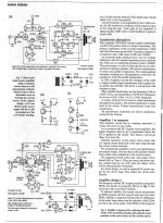
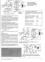
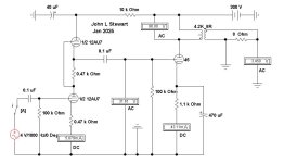
Schematic & some test results of the Hammond Choke cathode coupled, self Inverting Amplifier.
More later as I pull this out of the archives. I'm surprised no one recalls all this, was here on DIY during
2017, 🙂 in detail.
The front end, not shown on the schematic is a triode connected 6AU6.
More later as I pull this out of the archives. I'm surprised no one recalls all this, was here on DIY during
2017, 🙂 in detail.
The front end, not shown on the schematic is a triode connected 6AU6.
Attachments

The reason why designers prefer direct coupling over capacitor coupling is to get rid of the masking effect of capacitors. Anyone who is familiar with both and using his ears can perceive this. Especially when using high quality dacs ( in the case of cd players) and high quality pick up cartridges this phenomenon becomes apparent: there is increased transparency with dc coupling.
You can find numerous examples of direct coupled single ended designs on internet but very few pushpull ones. That is the reason why I wanted this amp posted. Unfortunately all reactions so far focus on different selfinverting output tube possibilities - requiering capacitor coupling! It's also not a tutorial about maximizing output power performance ! All I wanted was to stress the audible advantages of dc coupling and to realize this with simple means.
.

Likely hundreds of capacitors are in the recording and mixing equipment used to make the actual recording…
Regards, Gerrit
Regards, Gerrit
Please explain, based on science.the masking effect of capacitors
Best regards!
When the capacitance matches the load impedance there will be no frequency response or phase issues in the pass band.The reason why designers prefer direct coupling over capacitor coupling is to get rid of the masking effect of capacitors. Anyone who is familiar with both and using his ears can perceive this. Especially when using high quality dacs ( in the case of cd players) and high quality pick up cartridges this phenomenon becomes apparent: there is increased transparency with dc coupling.
DC Coupled PP Amp. Next time ask 6A3 to find it for you.
He will never show us his test results from self inverting amplifiers,
since he did not do the work. Ever!😀
He will never show us his test results from self inverting amplifiers,
since he did not do the work. Ever!😀
Attachments

BS. Where are the photographs? No test results, no amplifier. And No Schematics, ever!I have done self inverting amplifiers like that, with RC coupling, 0V bias grid, a 5H 200mA Hammond choke,
You got the 5H Hammond Choke information from my notes.
All reported in great detail on DIY in 2017.😀
At the 2008 VSAC, I presented a phase inverter with 6C45pi triodes, a bifilar wound pp to pp interstage from Jack Elliano, and a Hammond 5H 200 mA choke as the CCS for the inverter.
The interstage drove a pair of 300B output tubes, driving Jack Elliano's pp 6k p-p output transformer.
This was all part of a comparison of pp 300B versus pse 300B tubes.
A second amp was parallel 6C45pi, jack elliano interstage, parallel 300B, and a 3k SE output transformer.
this was a 2 part presentation, first with screen and talk, then another room ready for sound using those amplifiers.
Do not complain to me about not posting pictures, schematics, and a comparative listening session. I did my part, where were you?
Note: Nobody told me about a Hammond choke, I selected it all by myself.
If you did not see it, sorry that last VSAC was in 2008.
Some chose not to pay $165 for 3 music presentations, many seminars, and 3 meals.
For $40? a day you got to see the equipment rooms and the hobby room. No seminars for the cheapskates.
Not enough people paid $165, their unwillingness to spend the $165, was one reason that there never was another VSAC.
$0.03
Adjusted for inflation
Last edited:
You can put the guts of your presentation here on DIY, just as many others post evidence of their work.If you did not see it, sorry that last VSAC was in 2008.
Need schematics, comparative test results, parts lists, test equipment that was used & so on.
Let the folks on DIY decide whether your efforts were worth the price of admission. 🙂
For you & others, why did I use 5H?
Also, not to worry the people who complain about "sand" contaminating their valve amps, almost all recordings post the mid-1970s will have been recorded on transistor based equipment anyway...😉Likely hundreds of capacitors are in the recording and mixing equipment used to make the actual recording…
Regards, Gerrit
kind regards
Marek
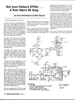
My first recollection of 6A3sUMMER’s work was an article in Issue #10 of Joe Robert’s Sound Practices magazine, Winter of 1995. 6A3sUMMER, a.k.a Dave McDonald & his buddy Matt Kamna had managed to reduce an otherwise perfectly good Dynakit into an SET pile of debris. Made me wonder a lot about where these people were coming from. And why Joe Roberts would publish such an article.
I noticed a few errors in other articles published on occasion & asked Joe R about this. He told me privately that some of his contributors often had problems getting their projects to work. I left it at that & moved on.
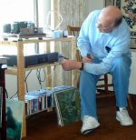
So here are some items on Dave & his testing of a loudspeaker with a simple amplifier he had built with pieces of other amplifiers. This particular sample is a no brainer. But no indication of what some serious tests would look like. Dave is 79 now, this photo from 2018 so he would have been about 50+.
I noticed a few errors in other articles published on occasion & asked Joe R about this. He told me privately that some of his contributors often had problems getting their projects to work. I left it at that & moved on.
So here are some items on Dave & his testing of a loudspeaker with a simple amplifier he had built with pieces of other amplifiers. This particular sample is a no brainer. But no indication of what some serious tests would look like. Dave is 79 now, this photo from 2018 so he would have been about 50+.
Attachments


I will give a response to jstewart9's Post # 30.
Mr Stewart's contributions both to Tubes / Valves, and magazines are many, and they are informative and educational, as well as historical and full of conceptual helps.
Thank you Mr. Stewart!
1. My complete set of presentation files from VSAC 2008, are buried inside a DEAD MacBook computer.
Photos, schematics, sentences, all gone!
Sorry, I did not back up those files.
If you were not at VSAC 2008, it is not my fault.
It is not my fault that the overworked MacBook computer had its hard drive replaced.
(I never claimed to be a computer geek, and never claimed to be a software geek, never claimed to backup all my files).
2. When I decided to use a choke as a CCS in phase inverters, I had 2 different chokes that I owned, I had to choose one of them.
20H @ 100mA, and 5H @200mA.
These chokes are typically used in full wave B+ power supplies (100Hz or 120Hz full wave frequencies).
The 20H has 4 times more inductance, but at 1/2 of the current of the 5H choke.
The desire was to have the choke useful down to 40Hz or better.
120Hz/40Hz = 3:1
The 5H choke is less likely to saturate on a 40Hz signal, versus the 20H choke which has more turns on a smaller set of laminations.
At high frequencies, the distributed capacitance might be a factor, since it shunts the CCS capability.
The 5H has less distributed capacitance than the 20H.
Now you know why I used the 5H choke.
3. I attempt to teach concepts and logical thinking; even though the actual circuit may not be very practical.
4. Some of my earliest practical experince:
During my 2 years on a US Naval Destroyer in the middle of the Pacific Ocean, and in Gulf of Tonkin, I was one of the few electronic technicians who kept the LF, HF, VHF, and UHF transmitting and receiving equipment in working order (even without the proper parts to accomplish the repair).
If you have never had such a trial by fire, you simply did not have the opportunity. That is not your fault.
We all come from different backgrounds.
Accepting others shortcomings is just as important as recognizing their strengths.
$0.03
Adjusted for inflation, and also for changing rates of money exchanges across country borders.
Post # 32
Here is the first response of many to that post:
Issue #10 of Joe Robert’s Sound Practices magazine, Winter of 1995.
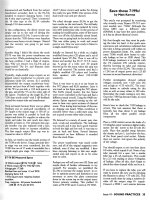
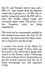
That article was 5 columns wide, only 3 columns were posted in Post # 32
Two columns of explanation were not posted, but here are the test results that were with the extra text:
10 Watts, 5% THD @ 1kHz
6 Watts, 1% THD @ 1kHz
Voltage gain 17.5 dB
Residual hum and noise 1.2mV RMS
Damping factor 3.8
1 kHz square wave response looked excellent
Freq. response - full power bandwidth -3dB @ 15Hz and 60 kHz.
Then EL34s were paralleled (PSE)
16 Watts @ 5% THD
14 Watts @ 1% THD
$0.03
Adjusted for inflation
Here is the first response of many to that post:
Issue #10 of Joe Robert’s Sound Practices magazine, Winter of 1995.
That article was 5 columns wide, only 3 columns were posted in Post # 32
Two columns of explanation were not posted, but here are the test results that were with the extra text:
10 Watts, 5% THD @ 1kHz
6 Watts, 1% THD @ 1kHz
Voltage gain 17.5 dB
Residual hum and noise 1.2mV RMS
Damping factor 3.8
1 kHz square wave response looked excellent
Freq. response - full power bandwidth -3dB @ 15Hz and 60 kHz.
Then EL34s were paralleled (PSE)
16 Watts @ 5% THD
14 Watts @ 1% THD
$0.03
Adjusted for inflation
My response to Post # 27,
I do not search on the web to find DC coupled amplifiers, so I do not post the links for those who do not do their own search.
Those who are interested can do their own searching.
I do not search on the web to find DC coupled amplifiers, so I do not post the links for those who do not do their own search.
Those who are interested can do their own searching.
No sooner done then said. Joe Roberts Sound Practices magazine is a very good resource.That article was 5 columns wide, only 3 columns were posted in Post # 32
Back copies were available for quite a while. Definitely worth having the complete
set in the library of any serious Audiophile.👍🙂
Attachments
That was from my archive, no iNet search at all.I do not search on the web to find DC coupled amplifiers, so I do not post the links for those who do not do their own search.
Those who are interested can do their own searching.
Do you have any kind of library at all??? 🙂 🙂 🙂
Odd that you should mention that. In 1948 at 15 yrs old, still a HS student I got a job in the paint shopIf you have never had such a trial by fire, you simply did not have the opportunity.
of the DeHaviland Aircraft Co in the Toronto suburb of Downsveiw. Working overtime one night, some of the paint shop crew including yours truly were cleaning out the bilge of a PBY using compressed air guns on hoses that sprayed some kind of cleaner
We wore masks supplied by compressed air on the end of air hoses, The cleaner was combustible, an extension light fell & broke, So a flash fire, I was in the compartment ahead of the bubbles.
Two of the guys went up thru an escape hatch, I went back thru the bulkhead, there was a stand
adjacent to the aircraft, I got out. My coveralls were on fire. Two of the guys outside the aircraft piled me into a car for a ride to the hospital where I was a guest for a while.
Worst part was getting the bandages off, just ask anyone who has gone thru that experience,
Attachments
Last edited:
Unfortunately most of the reactions deflect from the reason why I wanted this schematic to be published in the first place. Nonetheless I"ll comment on some of them.
Somewhere in the late 50 ties or 1960 an English engineer published an article about selfinverting tube applications. His conclusion: The cathode R should be at least 5x the nominal value for good phase inversion. The nominal value for EL84 PP (trioded) is 270 ohms (Vb 300V). I used 1k8 which is ample above 1k35.
My experience with both cap coupled and direct coupled amps is that the direct coupled ones have the highest transparency which I consider the most important property of a high quality sound system. That's why I wanted the driver tube direct coupled with the power tubes.
Thanks to the high amplification factor of the 84 (19) we don't need a very high dc of the driver tube. We don't need a very high cathode R and the power loss across the 1k8 is not excessive.
From my experience we don't need very high power in the living room usually no more than a few watts. To get the most power out of a pair of tubes was not the issue here; the aim was to get the highest sound quality with simple means.
- Home
- Amplifiers
- Tubes / Valves
- EL84 Push-Pull direct coupled by KeesB