I followed your advice and tried to make changes ... this is the result, how about?
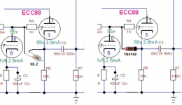
Like i advised before: Because of the maximum cathode to heater voltages of the ECC88 (they differ per triode), you should change the two triodes of the ECC88 around. Use pins 6, 7 and 8 (maximum cathode to heater voltage = 50 V) for the first stage and pins 1, 2 and 3 (maximum cathode to heater voltage = 150 V) for the second stage. Pin 9 (= internal screen between the two triodes) should be connected to ground.
Like i advised before: Because of the maximum cathode to heater voltages of the ECC88 (they differ per triode), you should change the two triodes of the ECC88 around. Use pins 6, 7 and 8 (maximum cathode to heater voltage = 50 V) for the first stage and pins 1, 2 and 3 (maximum cathode to heater voltage = 150 V) for the second stage. Pin 9 (= internal screen between the two triodes) should be connected to ground.
Attachments
rufus74pz,
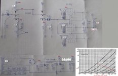
Looks like a very good performance.
This is without any negative feedback, except the unbypassed output tube cathodes, right?
With no bypass capacitor(s) on the output tubes cathodes, what is the damping factor?
Then, with bypass capacitor(s) on the output tubes cathodes, what is the damping factor?
Thanks!
Hello
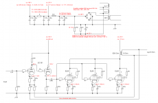
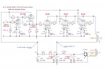
I forgot to add that PSE4P1L has capacitors in the cathodes of 4P1L tubes because here it is the opposite without THD capacitors it is higher. I gave an example of how a capacitor changes the distribution of harmonics and THD. I often use a diode in the input tubes cathodes but it is not so easy to find the right input tubes then the resistor or resistor plus capacitor is left. I apologize for littering the subject.
Piotr
Hi aria,
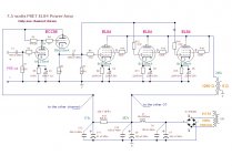
The schematic looks fine to me now. But don't you need a volume control? If so, you can put a potentiometer (log type) in place of the 220K grid resistor of the first stage.
Edit: I advise you to put gridstopper resistors to the controlgrids of all the tubes. A value of 1K will do. You allready have gridstoppers at the screengrids of the EL84's which is good (in that position 100 Ohm is fine).
Good luck with the build!
Last edited:
Hi aria,
The schematic looks fine to me now. But don't you need a volume control? If so, you can put a potentiometer (log type) in place of the 220K grid resistor of the first stage.
Edit: I advise you to put gridstopper resistors to the controlgrids of all the tubes. A value of 1K will do. You allready have gridstoppers at the screengrids of the EL84's which is good (in that position 100 Ohm is fine).
Good luck with the build!
Tks Robert
I would like to use it as a power amplifier using a pre that also has a phono stage ... at the beginning the idea was to be able to also have the alternative of connecting it as an amplifier for medium and high frequencies and to use an amplified subwoofer for low , both connected to a pre so that you can have about fifteen total watts with the help of a pair of biwired loudspeakers. But now I acquired a pair of 96 dB loudspeakers, so I may not need that power ... the only drawback is that those loudspeakers have a 16 ohm impedance.
When you switch the amp on, there is quasi imediately high voltage with solid state rectifiers.The tubes are still cold, no current and no voltage drop on the resistors.Resulting in 250V (and more) between grid and cathode of the cathode follower.Not very healty.
Two possible remedies.
Mona
Two possible remedies.
Mona
Attachments
Switching diodes are ready!
As for my project, making more accurate measurements with 2 more reliable testers, I discovered that my OT has only 2 options available and both are not the optimal ones: Turns Ratio 9.5: 1 and 13: 1... I think I will have to opt for the second one by decreasing Iq to 37.8 ... I will have 1 watt more and, I imagine, a lot of distortion as a companion ...
As for my project, making more accurate measurements with 2 more reliable testers, I discovered that my OT has only 2 options available and both are not the optimal ones: Turns Ratio 9.5: 1 and 13: 1... I think I will have to opt for the second one by decreasing Iq to 37.8 ... I will have 1 watt more and, I imagine, a lot of distortion as a companion ...
The 13:1 ratio gives 1350 Ohm as the primary load when the secondary load is 8 Ohm.
Power triodes, and other power tubes connected as triode, are not so critical when it comes to their loading. Maximum power will be achieved when the load resistance is twice the internal (dynamic) resistance of the tube. I do not think that distortion will be affected much if you higher the load; distortion could even get a little bit lower.
In your amplifier, each EL84 will see 3 x 1350 = 4050 Ohm. The internal resitance of a triode connected EL84 is about 1700 Ohm (the mu between g2 and g1 is 19 and S = 11 mA/V, so Ri = mu / S = 1700 Ohm) so for maximum power one EL84 should see 3400 Ohm (the datasheet gives 3500). You are close to this value so you will be fine.
You are right, the numbers will change somewhat. But 4050 instead of the 3500 in the Mullard datasheet does not matter much for power triodes.
Whatever primary impedance you pick . . . That impedance is only there when you connect a resistor value to the output tap that equals the rated impedance of that output tap (such as an 8 Ohm resistor on an 8 Ohm tap).
Get that in the ball park, but then do not worry about it too much.
And, even with a pure resistor on the 8 Ohm tap, the transformer will present an inductive load to the tubes at very low frequencies (primary inductance) , and will present a capacitive load at very high frequencies (primary distributed capacitance)
The tubes will see an even larger variation of impedance when you connect a real loudspeaker.
If you want the tubes to see an exact impedance, you need to design a loudspeaker that has a constant totally resistive impedance versus frequency across the complete audio frequency range. There are very few of those loudspeakers.
In reality, the loudspeaker will have frequencies that appear capacitive, inductive, resistive, and a combination of capacitive/resistive or inductive/resistive at various frequencies.
The load line of the frequencies that are pure resistive is a straight line.
The load line of the frequencies that have either capacitive or inductive impedances, will not be a straight line . . . The load line will be an Ellipse, not a straight line.
It all works out better than you might expect.
It is like the Bumble Bee that according to science can not fly, but it ignores those calculations, and flies anyway.
By the way, for Elliptical Load Lines, a push pull amp is able to deal with an elliptical load line much better, versus a single ended amp deals with an elliptical load line.
But I like both single ended amps, and push pull amps.
Remember the flying bumble bee.
Last edited:
Hi Aria,
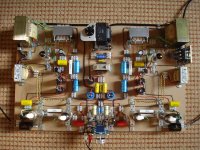
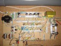
If you at first use a flexible way of building, you can try different possibilities before you make a final choice.
Two examples:
The first is an OTL amplifier (no hum/noise at all and working very good).
The second is a guitar amp i gobbled together at the start of my rediscovery of this hobby. Hum and noise were present but i did not understand the importance of preventing groundloops at the time, and at guitar levels this type of building (no shielding by a metal chassis) is sensitive for hum and noise. But at line levels you will hardly have noise or hum issues.
Greetings,
Robert
Attachments
Whatever primary impedance you pick . . . That impedance is only there when you connect a resistor value to the output tap that equals the rated impedance of that output tap (such as an 8 Ohm resistor on an 8 Ohm tap).
Get that in the ball park, but then do not worry about it too much.
And, even with a pure resistor on the 8 Ohm tap, the transformer will present an inductive load to the tubes at very low frequencies (primary inductance) , and will present a capacitive load at very high frequencies (primary distributed capacitance)
The tubes will see an even larger variation of impedance when you connect a real loudspeaker.
If you want the tubes to see an exact impedance, you need to design a loudspeaker that has a constant totally resistive impedance versus frequency across the complete audio frequency range. There are very few of those loudspeakers.
In reality, the loudspeaker will have frequencies that appear capacitive, inductive, resistive, and a combination of capacitive/resistive or inductive/resistive at various frequencies.
The load line of the frequencies that are pure resistive is a straight line.
The load line of the frequencies that have either capacitive or inductive impedances, will not be a straight line . . . The load line will be an Ellipse, not a straight line.
It all works out better than you might expect.
It is like the Bumble Bee that according to science can not fly, but it ignores those calculations, and flies anyway.
By the way, for Elliptical Load Lines, a push pull amp is able to deal with an elliptical load line much better, versus a single ended amp deals with an elliptical load line.
But I like both single ended amps, and push pull amps.
Remember the flying bumble bee.
the metaphor of the bumblebee is beautiful...
Both are compromises, as are all the components that allow us to listen to music at home ... some things that the PP can do, the SE can't do and vice versa ... my choice in trying with the SE it is simply linked to the greater simplicity of realization ... even if I have a belief, perhaps wrong, that the less traveled the current will do, closer the signal will be to a certain naturalness of exposure.
Hi Aria,
If you at first use a flexible way of building, you can try different possibilities before you make a final choice.
Two examples:
The first is an OTL amplifier (no hum/noise at all and working very good).
The second is a guitar amp i gobbled together at the start of my rediscovery of this hobby. Hum and noise were present but i did not understand the importance of preventing groundloops at the time, and at guitar levels this type of building (no shielding by a metal chassis) is sensitive for hum and noise. But at line levels you will hardly have noise or hum issues.
Greetings,
Robert
Hi Robert
I had a bad experience with an OTL, I am not attracted to the realization. Instead, it is in my future thoughts to build a double transportable SE amplifier, one for guitar and one for microphone following the patterns of a brand that you will surely know better than we, being you and it both Dutch.
Aria
My point was not OTL, guitar or what have you. My point was to suggest a flexible way of building, so you can try out different options for your amplifier, before you settle on what sounds best for you. You started this thread almost a month ago but you do not seem to be getting much further.
My point was not OTL, guitar or what have you. My point was to suggest a flexible way of building, so you can try out different options for your amplifier, before you settle on what sounds best for you. You started this thread almost a month ago but you do not seem to be getting much further.
Then I didn't understand what you mean by "flexible".
However, I went on ... I started this thread with a largely wrong schematic and now, thanks to the help of all of you, I have a correct schematic that has evolved gradually taking into account also the materials I have ... in the meantime i started building it and I learned more about what I'm doing, it doesn't seem small to me.
Attachments
Last edited:
- Home
- Amplifiers
- Tubes / Valves
- EL84 Parallel SE