What is the correct value for R39 for EL84 ? The Dec 2018 BOM shows 33K for EL84 and 15K for EL34. Some later BOM's only show 15K.
If it matters, the transformer that will be used for the bias is an AN-0130, 10VA 30V, with both 30V secondaries in series for 60V.
If it matters, the transformer that will be used for the bias is an AN-0130, 10VA 30V, with both 30V secondaries in series for 60V.
By simply substituing the 12AX7 with a 12AT7, the results at 13 Wrms are:
That's a pretty handy result, especially in the face of no further optimisation. I'm expecting that the CCS should be rigged for more like 3ma per side and that the 220k should be reduced, but I'm no expert.
I wonder how much of that reduced distortion is just down to the output stage (and transformer) not being driven quite so hard. ie if both examples were driven so that the output is 15W, would the 12AX7 distortion come down.
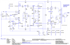
BTW. It looks like your global feedback is through 220k, which is a lot larger than the reference circuit. Is this the circuit you simulated?
[Edit] Never mind, I see that the the leg to ground is increased too.
I should just try to replicate your sim setup and stop asking questions 🙂
Last edited:
A question for those with greater knowledge. If I were to use the BH PSU board, the bias and driver voltages differ from the EL84 schematic. The psu board sets bias at -100V and the driver voltage at +15V. Is this OK for the EL84 version of the design or are those voltages specific to the EL34 and it would be better to use the onboard option to set the bias at -65V and the driver at +65V ?
thanks
EDIT:
2 useful links to the PSU details
1. schematic / BOM
2. implementation with DC/DC booster
thanks
EDIT:
2 useful links to the PSU details
1. schematic / BOM
2. implementation with DC/DC booster
Last edited:
I would scale the whole 220k+47k based on the ratio of 12ax7 and 12at7's rp, in order to keep the rp vs Rl ratio constant.That's a pretty handy result, especially in the face of no further optimisation. I'm expecting that the CCS should be rigged for more like 3ma per side and that the 220k should be reduced, but I'm no expert.
I can simulate it, just a matter of reducing the signal at the input of my version. Just note that my version has 23% UL andnot 43% like suggested here.I wonder how much of that reduced distortion is just down to the output stage (and transformer) not being driven quite so hard. ie if both examples were driven so that the output is 15W, would the 12AX7 distortion come down.
just keep the ratio the same, or eliminate it and: increase R16 to reduce EL84's distortion and rp, increase the resistance on the cathode of each side of the PI to increase local feedback for the PI.BTW. It looks like your global feedback is through 220k, which is a lot larger than the reference circuit. Is this the circuit you simulated?
[Edit] Never mind, I see that the the leg to ground is increased too.
I appreciate your questions, many others can partecipate and share their experience.I should just try to replicate your sim setup and stop asking questions 🙂
Here it is my version of the BH EL84 with 330 V B+ and the following results (simulated) at 22 Wrms:
Total Harmonic Distortion: 2.260755%(2.271256%)
Thanks. I switched to your transformer and the STW11NM80 MOSFET and realised I had one of the MOSFETS upside-down.
20.6W: Total Harmonic Distortion: 2.688109%(2.692499%) - slightly higher than yours.
1W: Total Harmonic Distortion: 0.126749%(0.126763%)
Attachments
There is no correct value, it depends on the voltage at which you supply the board with bias.What is the correct value for R39 for EL84 ? The Dec 2018 BOM shows 33K for EL84 and 15K for EL34. Some later BOM's only show 15K.
So you'll have around +-40 Vdc. I'ts fine for EL84.If it matters, the transformer that will be used for the bias is an AN-0130, 10VA 30V, with both 30V secondaries in series for 60V.
Suggested values are three times the bias voltage on the negative side. I've set them at +-35 Vdc.A question for those with greater knowledge. If I were to use the BH PSU board, the bias and driver voltages differ from the EL84 schematic. The psu board sets bias at -100V and the driver voltage at +15V. Is this OK for the EL84 version of the design or are those voltages specific to the EL34 and it would be better to use the onboard option to set the bias at -65V and the driver at +65V ?
That's the raw bias voltage.Thanks zintolo. Is that with the 33K or 15K?
R39 forms a voltage divider with the two bias pots in parallel, so 25k.
Consider to have 1,5 times the needed biasing voltage as the lowest possible voltage for pot, so 18V approxiamtely, that is 45% of the raw bias voltage, so the needed resistance in series with 25k would need to be 27k. That's the value for R39. 33k would fit too, 39k is a bit tight.
Thanks that certainly clears things up.
May I ask how you reached the raw voltage? It looks like a half wave rectification with a single diode? And then some voltage drop across the 270R resistor?
May I ask how you reached the raw voltage? It looks like a half wave rectification with a single diode? And then some voltage drop across the 270R resistor?
Exactly. Just consider that the current flowing on the negative side is the drivers current (2 x 0,7/390 = 3,5 mA circa) plus the PI one (1,2 mA). The positive side is just the drivers one.
Set R20 and R21 to 1 MOhm. Then try to lower EL84's cathode resistors to 1 Ohm.Thanks.
20.6W: Total Harmonic Distortion: 2.688109%(2.692499%) - slightly higher than yours.
Just consider that the values you set now on the output transformer are with 23% UL. Are you using 23 or 43%? Curves change significantly.
Just consider that the values you set now on the output transformer are with 23% UL. Are you using 23 or 43%? Curves change significantly.
Good point. I'm pretty sure the Toroidy OPTs I've bought are 43%. I'll check.
Standard toroidy are 43%, I can confirm you.
Mines are custom built by them under my specs.
To calculate the inductances of each section, just consider that it is proportional to the square value of the windings, so the screen tap at 43% is (0,43/2)^2 times the total value.
Mines are custom built by them under my specs.
To calculate the inductances of each section, just consider that it is proportional to the square value of the windings, so the screen tap at 43% is (0,43/2)^2 times the total value.
Yes. 43%. TTG-EL84PP - Tube output transformer [8kOhm] 2xEL84.
Primary inductance is 404H. I'll do some reading and math and see if I can update my simulation accordingly.
Primary inductance is 404H. I'll do some reading and math and see if I can update my simulation accordingly.
I suggest you to arrange an excel file, especially if you want to play with simulations, because it saves you alot of time.
A question for those with greater knowledge. If I were to use the BH PSU board, the bias and driver voltages differ from the EL84 schematic. The psu board sets bias at -100V and the driver voltage at +15V. Is this OK for the EL84 version of the design or are those voltages specific to the EL34 and it would be better to use the onboard option to set the bias at -65V and the driver at +65V ?
thanks
The PS board was developed to accommodate the negative bias for “big power tubes”, like the KT88s, which could not be properly biased by the initial PCBs designed for EL84s. Unless you really want the turn-on delay feature, you do not need the PS PCB with your BHEL84.
Thank you all for the replies - I will set up a tube regulated psu as I had originally planned, I was going to use the board because of these other voltages but if not needed, then it makes things more simple for me.
I'm not affiliated with them, but I've recently found this interesting item on ebay (perfect for Yves Monmagnon's ECL86 amp):
Tube Amplifier Switch Power Supply Board Transformer 60W For Audio Amplifier | eBay
Product size: 120mmX55mm
Opening size: 112mmX47mm
Input voltage: AC 100V-265V
Output voltage: Output the first group: DC 6.3v /4. 5A
Output the second group: DC 250v /0.15A
Output power:60W
Working frequency: 65KHZ
Tube Amplifier Switch Power Supply Board Transformer 60W For Audio Amplifier | eBay
Product size: 120mmX55mm
Opening size: 112mmX47mm
Input voltage: AC 100V-265V
Output voltage: Output the first group: DC 6.3v /4. 5A
Output the second group: DC 250v /0.15A
Output power:60W
Working frequency: 65KHZ
Here the results at 18 Wrms without gnfb and with a 12AY7 (drop in without optimisation):
Code:
Harmonic	Frequency	 Fourier 	Normalized	 Phase  	Normalized
 Number 	  [Hz]   	Component	 Component	[degree]	Phase [deg]
    1   	1.000e+03	1.722e+01	1.000e+00	   -0.34°	    0.00°
    2   	2.000e+03	1.108e-02	6.431e-04	  -87.24°	  -86.91°
    3   	3.000e+03	2.057e-01	1.195e-02	   -7.94°	   -7.60°
    4   	4.000e+03	1.854e-03	1.077e-04	   84.03°	   84.37°
    5   	5.000e+03	8.960e-02	5.203e-03	 -161.06°	 -160.72°
    6   	6.000e+03	1.660e-04	9.641e-06	   70.79°	   71.12°
    7   	7.000e+03	7.194e-02	4.177e-03	  -16.33°	  -15.99°
    8   	8.000e+03	1.231e-04	7.147e-06	   67.16°	   67.50°
    9   	9.000e+03	4.785e-02	2.778e-03	  -23.68°	  -23.34°
Total Harmonic Distortion: 1.397771%(1.462189%)- Home
- Amplifiers
- Tubes / Valves
- EL84 Amp - Baby Huey