.....Try 470 Ohms or even 1K in lieu of the 150 Ohms.
Ian,
I have tried your suggestion but unfortunately it didn't help. I tried 470 ohm and 1K but still with the oscillation.
The DC settings I think are correct. With an U+ of 306V the settings are as follows.
ECC803:
pin 1 and 6, 124V
pin 3, 0,95V
pin 8, 0,82V
Voltage CCS across 1K resistor is 1,3V. Current is then 1,3mA which should be fine.
EL84:
pin 7, 302V
pin 9, 301V
UL-Tap, 304V
pin 3, upper tube 10,9V, lower tube 11,3
Voltage bias block across 16 ohm resistor is 600mV. Current is then 37,5mA which is fine too, I think.
Both channels have about the same settings.
Heatings ECC803 and EL84 are ac 6,27V.
The chassis is connected with an 10 ohm resistor to earth.
Output is not connected to earth.
Everything should be all right. I am a bit lost. Could the ECC803 be the problem, since this tube has a high bandwith? Or maybe the UGT?
I have bought the UGT from a local store. He said this is a good UGT for an EL84 PP. But I forgot to ask what the Raa, % of UL connection and sec. impedance were.
Thanks in advance.
Rene
It may be a problem with the layout.
A few generic hints: make sure that all the grid stoppers (on g1 e g2 of all tubes) are mounted right on the tube socket. The by-pass capacitors for all the CCSs must be installed as close as possible to the cathodes and then joined together to the ground star point. Minimize the lenght of the feedback loop(s) connections. Be careful of parastitic couplings between different connections. Avoid wires running parallel to each other (except for those bringing "to and from" current path of the same signal, which should be twisted together).
A few generic hints: make sure that all the grid stoppers (on g1 e g2 of all tubes) are mounted right on the tube socket. The by-pass capacitors for all the CCSs must be installed as close as possible to the cathodes and then joined together to the ground star point. Minimize the lenght of the feedback loop(s) connections. Be careful of parastitic couplings between different connections. Avoid wires running parallel to each other (except for those bringing "to and from" current path of the same signal, which should be twisted together).
Unixman,
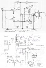
The grid stoppers are directly connected to the tube sockets. I have a different lay-out for the CCS that might not be ideal. I have put the two 470 ohm resistor and the and 1k Bal. on the printcard instead of directly connected to the tube sockets. See attached image.
Eventually I put a capacitor of 1nF across the Anode (pin7) and grid 2 (pin9) which stops the oscillation. I am happy about that!
The sounds seems a bit more transparent, cleaner and the high's are brighter.
Regards,
René
Attachments
Rene,
Somewhere earlier i this thread zobels from anode to screen on the output tubes were discussed. A 1k + 1n8 connected directly across the anode and screen transformer connections were IIRC what was used. The screen connection needs tgo be at the transformer side of the screen resistor. Try searching for it.
Cheers,
Ian
Rene,
I did the search for you - look back at page 83 and posts by myself and Yves "dupy", in particualr posts #815, #824, #827
These relate to UL instability and the adding of anode to screen zobels across the transformer connections.
Cheers,
Ian
I did the search for you - look back at page 83 and posts by myself and Yves "dupy", in particualr posts #815, #824, #827
These relate to UL instability and the adding of anode to screen zobels across the transformer connections.
Cheers,
Ian
Thanks Ian,
One question though.
The amp sound very nice now with only the 1nF cap between the screens and the anodes. But a zobel, like suggested in the earlier posts, means a resistor and C in serial. So is it really necessary to put the 1K resistor in as well? Maybe this benefits the stability.
René
One question though.
The amp sound very nice now with only the 1nF cap between the screens and the anodes. But a zobel, like suggested in the earlier posts, means a resistor and C in serial. So is it really necessary to put the 1K resistor in as well? Maybe this benefits the stability.
René
Rene,
Yes - I would try adding the 1K in series with the 1nF cap. Easy to take out again if you don't like it or if the instability comes back.
This is an area where I need to do a bit more work to determine "optimum" result.
I had always intended to hook up the sig gen and oscilloscope and do full amplitude and phase plots of the amp with and without UL Zobels but got lazy and haven't done it yet (well actually I got sidetracked building a guitar amp).
I had halted mods on the most recent BH as it had reached the point where I need to upgrade my sources and preamp to tell if things were getting better or not.
A new CD Player - Onkyo with Terra Firma Clock and audio section upgrades arrived today (2 hour ago) so we are back in buisiness and I'm Aussie$1600 (about US$1700) poorer. Just need to get stuck in to the replacement preamp build. For a new preamp Allen Wright sent me his latest schematics for the SPV2 about 2 months before he died. They were provided on a "Comercial in Confidence" for my personal use ONLY basis, so please, no-one ask to have them posted because I won't.
Off for the next 4 days - will check back in after that.
Cheers,
Ian
Last edited:
Ian,
I am sorry to hear about Allen Wright.
I think I am just going to do that because it is easy to try it. And if the results are not satisfactory I indeed put it back again in the previous state.
Regards,
René
I am sorry to hear about Allen Wright.
I think I am just going to do that because it is easy to try it. And if the results are not satisfactory I indeed put it back again in the previous state.
Regards,
René
There is an article hereon the SVP-2.:
http://www.vacuumstate.com/fileupload/vacuum_state_low_res.pdf
As complex as it looks I doubt I would ever attempt anything near that level.
Although I am tempted to build a version of his FVP5.
I too will deeply miss him in passing even though I never had correspondence with him. His influence is widespread.
Gimp,
The SVP2 is the "modern" FVP5A - very similar schematic.
The new Onkyo CD player with the Vacuum State Terra Firma Lite Clock and the audio section upgrade was a revelation - I don't regret spending the money. Hard to describe the sound change between this and my old Dennon, the initial word that comes to mind is "softer" but thats misleading - there is a harsh edge (which I hadn't really noticed) which is just not there with the Onkyo. Very articulate and just more "organic". This is my birthday present to myself.
Rene,
How did you go with the zobel mod?
Cheers,
Ian
No progress on the weekend - an emergency repair on a friends guitar amp instead.
Last edited:
Ian,
I have not tried it yet, because I first wanted to enjoy the music for a couple of days. Tomorrow I have invited a friend for listening and compare it to his Copland EL34 amp. I am specially curious about the body and strength of the low frequencies.
After that I am going to add the zobel. I will let you know about the differences.
Regards,
René
Hello all,
I'm in the process of building the modules for my fixed-bias Baby Huey and have a question about the -ve power supply for the EL84 bias/12AX7 CCS supply.
I was planning on closely following Ian's schematic which uses a small separate transformer for the -48V. However I have discovered the Power Transformer I have (James) has a 70V bias tap on the main secondary. It seems to be a no-brainer to use this tap as they have in dozens of classic tube circuits.
But... I would have to half-wave rectify it. I've been reading up on this type of rectification and I have to admit, the press is not good:inefficient, high ripple etc.
So the question is - will I be compromising the performance of the amp doing it this way?
I have the traffo to do a separate supply but it's another thing I have to squeeze into the chassis and if I don't need to use it then I'd rather not.
I don't think it would. Hundreds of thousands of great sounding amplifiers have used that technology.So the question is - will I be compromising the performance of the amp doing it this way?
Could it be improved on? Of course.
Bill,
Nothing drawn - basically use the fixed biased EL84 schematic and substitute EL34. Run at higher voltage - say +400 to +450 Volts and Output Trannies to suit.
However - if I were going to build a higher power version of the BH I would be tempted to go "the whole hog" and use KT88 at around 500V instead. I have trannies and tubes on the shelf to do this (one of these days).
Cheers,
Ian
Hi Ian,
Built my Baby Huey mostly out of job lots from Ebay so naturally I have a lot of left over parts including a quad of EL34's. I don't really need the extra power ( Audax aerogel speakers, smallish room ) so I think I'll take your advice and wait. As I have plenty of Philips ECL86's I will probably go down in power a little and build the original version. If I do I think I'll start a separate thread on it's build. ( This one has become epic...... 😀 )
I've been given a turntable so I have to build a phono preamp for the Baby first.
Brgds Bill
hidnplayr,
See post #179 page 18. Panos29 asked if PL84 could be used. I told him that I thought you could - no idea if anyone went ahead and made one using PL84.
I've only done EL84, 6V6 and ECL86 (6GW8) versions myself and have modified a Chinese EL34 amp to the BH circuit. I am aware that an EL80 (6M5) version also exists and the builder was very happy with it.
Cheers,
Ian
Cheers,
Ian
- Home
- Amplifiers
- Tubes / Valves
- EL84 Amp - Baby Huey