Insel prices went up quite a bit. I remember buying the TSL180 power Transformer for 43usd (10 years ago), now it is close to use 100. And this thread is old 🙂Here 80€ each more shipping.
Here are the schematics I have used. Attached also are test results of EL34 PP with TGL40 as pentode, UL and cathode feedback.Do you have any links to schematics using these?
If you are interested in power supply schematics I have used, I can post those too.
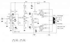
Essential with JJEL509 (=PL519) is to have regulated screen and -Ug1 voltages.
Attachments


The TSL180 power Transformer has this as well, along with 2* 3.2V. I think it is meant to be combined with these for eg 5V for rectifiers? But the no 6.3V anymore...Hello, there is a 2v 6A winding on the power transformer Indel tsl 180/001.IWhat is the use of this winding please ?
Hello,The TSL180 power Transformer has this as well, along with 2* 3.2V. I think it is meant to be combined with these for eg 5V for rectifiers? But the no 6.3V anymore...
comon winding for tube and rectifier filament ?...It looks strange, isn't it
They could build a 10v 0,6a winding instead of this on... Voltage network at home is 245v.
Hello,Here are the schematics I have used. Attached also are test results of EL34 PP with TGL40 as pentode, UL and cathode feedback.
If you are interested in power supply schematics I have used, I can post those too.
Essential with JJEL509 (=PL519) is to have regulated screen and -Ug1 voltages.
Can you explain the cathod feedback please ?
Quad II works with cathod feedback ,but it's different (and i don't understand it too)
No, no common winding for tube and rectifier - that would NOT be good for the tubes, sitting with their cathodes at B+ potential!Hello,
comon winding for tube and rectifier filament ?...It looks strange, isn't it
They could build a 10v 0,6a winding instead of this on... Voltage network at home is 245v.
I think either 6.3V for tubes, or 5V for rectifiers, not both.
I do not use it, and agree that it would indeed be better spent on eg this 10V buck/boost winding, a smaller power 6.3V winding, etc.
Here are the schematics I have used. Attached also are test results of EL34 PP with TGL40 as pentode, UL and cathode feedback.
If you are interested in power supply schematics I have used, I can post those too.
Essential with JJEL509 (=PL519) is to have regulated screen and -Ug1 voltages.
Hello ,
Yes , your power supply schematic interest me. Nice idea to use 6F12P for dynaco MK3.
Regards

Thanks a lot for sharing.Ici:
I will share soon my schematic,but perhaps in a other thread.
If you remember my first project was a gu50 PP.
But now the g807 PP project is already well advanced.
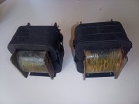
I owned a cheap strong a and strange pair of output transformers in a goodwill.
Have a look, windings mesures coming next,i must draw the schematic.
The iron is roughly the same size as the tgl 40/001 one.
Attachments
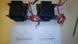
Voici donc le schéma, je les ai branché sur le réseau 245v et mesure 10,1v ac en sortie. Z est 4,7k.
Comme vous le voyez il y a un autre bobinage qui donne 55v. A quoi ça sert ?
Please.
Comme vous le voyez il y a un autre bobinage qui donne 55v. A quoi ça sert ?
Please.
Attachments

Hello,I can recommend this: Indel TGL40/001.
TGL 40/001 INDEL - Transformer: speaker | TME - Electronic components

It is rated for 40 W but is huge and has 180 VA core. And don't care about the frequency response specified by the manufacturer.
With some 10...14 dB of GNFB this reaches beyond 100 kHz.
Do you know if the TGL 40/001 can handle a 4 ohm load ,please ?
Regards
Try to check Hammond stuff
Walter
Walter
Do you know if the TGL 40/001 can handle a 4 ohm load ,please ?
Don-Audio has Hammonds in Europe, (1650NA would be the closest one I think), and prices lower than Digikey, and least when delivering to the UK.
There is also Toroidy in Poland:
https://sklep.toroidy.pl/en_US/p/TT...-4kOhm-2xKT88-2x300B-Push-pull-or-similar/563
That one also does both 4 & 8ohm
There is also Toroidy in Poland:
https://sklep.toroidy.pl/en_US/p/TT...-4kOhm-2xKT88-2x300B-Push-pull-or-similar/563
That one also does both 4 & 8ohm
Guys,Hammond 1650
I already have my TGL 40/001 transformer and i have builded my 807 monoblocks with a pair.
I just wanted to know if it was able to support a 4 ohm load.
Yes it will work with 4R but you will have 2K instead of 4K primary impedance. The output power will depend on the tubes you are using and their biasing condition. The power rating of the transformer alone will increase but insertion loss will increase as well respect to 8R load because the primary impedance is halved while source impedance and DC resistance of the windings stay the same.
It will work, but the reflected primary impedance will be 2K, while your output stage has been designed for a 4K load. It will probably distort quite a bit at higher power.I just wanted to know if it was able to support a 4 ohm load.
@jcalvarez, it might happen the contrary, lower distortion for the same output power but more distortion at low power. Likely more cross-over distortion. If it could work at all power levels, it will depend on the actual conditions. It could be adjusted or not, this will depend on the tuning possibilities one has with both the tubes and power supply.
- Home
- Amplifiers
- Tubes / Valves
- EL34 UL PP Transformer