Id expect the 807 to run out of current at high signal values, but the output stage can of course be tuned. My comment was about using the original schematics, voltages etc but just plugging a 4ohm speaker.

I assume it's the leak TL25 amp.
The 807 can work in class AB2 in both triode and pentode and so it's capable of high peak currents. UL is in the middle in terms of anode curves and so it is possible as well. Staying in class AB1, the current will be according to its UL curves and load. It will be less power respect to 4K load but not because it runs out of current.
The 807 can work in class AB2 in both triode and pentode and so it's capable of high peak currents. UL is in the middle in terms of anode curves and so it is possible as well. Staying in class AB1, the current will be according to its UL curves and load. It will be less power respect to 4K load but not because it runs out of current.
Attachments
To be honest, looking at the thread I'm not sure whether @Marco audio is designing something from scratch or based on a particular schematic voltages set etc, therefore I will shut up for the moment 🙂
it looks a lot like Imphy or Metalimphy transformersThanks a lot for sharing.
I will share soon my schematic,but perhaps in a other thread.
If you remember my first project was a gu50 PP.
But now the g807 PP project is already well advanced.
I owned a cheap strong a and strange pair of output transformers in a goodwill.
Have a look, windings mesures coming next,i must draw the schematic.
The iron is roughly the same size as the tgl 40/001 one.
Did you ever build that amp? Which OPT did you choose? Any performance data to share? THX 👍I plan to build a classic EL34 UL PP amp.
Essayer voir Sansui q50 q55.
Thanks a lotJe suppose que c'est la fuite de l'ampli TL25.
Le 807 peut fonctionner en classe AB2 à la fois en triode et en pentode et il est donc capable de courants de crête élevés. UL est au milieu en termes de courbes d'anode et c'est donc également possible. En restant en classe AB1, le courant sera en fonction de ses courbes UL et de sa charge. Ce sera moins de puissance par rapport à la charge 4K mais pas parce qu'il manque de courant.
 @Marco audio This is an English language forum, you must post in English. Check your translator settings, it is broken.
Hey all,
I am about to post a pair of new unused Indel TGL 40/001 output trannies in the swap meet...
I am about to post a pair of new unused Indel TGL 40/001 output trannies in the swap meet...
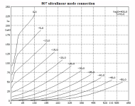
@artosalo,Here are the schematics I have used. Attached also are test results of EL34 PP with TGL40 as pentode, UL and cathode feedback.
If you are interested in power supply schematics I have used, I can post those too.
Essential with JJEL509 (=PL519) is to have regulated screen and -Ug1 voltages.
I am interested to know more about the EL34 schematic with cathode feedback using the Indel TGL 40/001 output transformer. Could you explain how you used the TGL40 output transformer in this application, given that it is specified for 8 Ohm secondary only.
If one examines the photo of the TGL40 connectors it shows terminals 1+2+3+4 are connected and likewise 5+6+7+8 to present a composite 8 Ohm secondary. I could not find more information on how these separate secondary coils (4 of them?) are rated. Which coils are connected in @artosalo ’s schematic for cathode feedback in the EL34 PP amp?
https://www.tme.com/au/en/details/tgl40_001/transformers-with-fastening/indel/tgl-40-001/
Thank you. Very clever approach and one that I plan to experiment with. Just wanted to be sure I understood correctly what you tried and tested. So, any of the 4 secondary coils could be picked for cathode feedback duties, or is there a preferred one.
Yes @rayma, I understood @artosalo to mean the four secondary coils have identical turn ratios. Since it is not possible in real life to have four windings that are identical in every respect due to different practical geometries of the coils, I wondered if there was a preferred one to use as feedback coil.
I never studied if there is difference between those 4 secondaries. Just used one for cathode feedback.
quadfilar ought to do it, Susan parker did it in her amps..Yes @rayma, I understood @artosalo to mean the four secondary coils have identical turn ratios. Since it is not possible in real life to have four windings that are identical in every respect due to different practical geometries of the coils, I wondered if there was a preferred one to use as feedback coil.
Antique Sound Labs use dual bay bobbins in winding thir OPT's, these ensures equal dc resistances, ang shunt capacitance is cut in half...
i have sonme of these 11460 dual bay bobbins i am making OPT's someday...
Last edited:
But why use one secondary winding for feedback? If all were paralleled we'd get the same feedback voltage and better coupling. ?
All good fortune,
Chris
All good fortune,
Chris
- Home
- Amplifiers
- Tubes / Valves
- EL34 UL PP Transformer