JojoD818 said:The leds doesn't have to be red but as long as the voltage drop is as specified.
that was my point. i understand that different LEDs have different voltage drops.
Tony said:
looks good!
btw, have you decided how to feed dc to the 6SN7/6SL7 heater? are going full wave rects? then you need 2 x 3amps rectifiers, 1N5402 is good here.
😀
So I can order the tranny with the 9-0-9V 2A winding right?
navin said:
that was my point. i understand that different LEDs have different voltage drops.
and they also vary from one manufacturer to another even for the same color leds. but I think this won't be too much of a critical issue since there is a 470 ohms trimpot to set the current.
navin said:
Now I am confused. I was given to understand that the only the 6SL7 really could use DC on the heaters.
Sorry Navin, not meant to confuse you. I did not mean that dc is wrong, just that if it is not clean, i.e. low ripple, say <0.5V and especially with rectifier spikes, you may induce more noise than you cure, or at least do no better than with ac. Perhaps someone else can clarify why dc is preferred on 6SL7 specifically, especially in a main amplifier - perhaps as said certain brands are more prone to ac induction than others. I have not used 6SL7 in this application for years, that is my tubes were NOS at the time. I only meant that in my experience I never had a problem with ac on heaters (in this application, as said).
If other members had different experiences it would help if they can detail it here. If it was done on this thread some time ago I cannot recall - sorry for missing it then.
Regards.
My exp with ac and dc heaters...
I've used ac and dc on heaters and found that with ac heating I have always had very low level hum . However this can be reduced to such low levels that it hardly matters at the listening position . The hum is audible a few inches from the speaker but not at 5 feet away. Speaker sensitivity abut 89db.
Dc was practically dead silent but needed the standard twin resistors from the heater supply lines to ground to achieve that.
I really could not make out any difference between ac and dc heaters. Some say you can hear it , but I didn't. Maybe I should make a dedicated test for this to check it out. ( Supposedly ac heaters sounding better -- and also improving the heater element life ).
With an overall negative feedback amplifier the effect of hum must be less.
It might be a good idea to have a 6.3 volt ac tap ( on load ) and something higher for use with a dc regulator and dc heater supplies. Then you can use ac ( very simple ) to start with and if you find it is not good enough , you can convert to regulated dc easily.
Cheers.
Re: My exp with ac and dc heaters...
I have asked them for the follow secondary taps.
370V AC, 1Amp, additional taps at 340V and 355V
3.15-0-3.15 AC 8A CT (for EL34 heaters)
9-0-9V AC 2A CT (for 6SL7 and 6SN heaters) to be rectified to DC
70V AC (no need for CT) 0.2A for bias...
12V AC 0.5A for delay ckt and relays
why 6.3V?
ashok said:
Dc was practically dead silent but needed the standard twin resistors from the heater supply lines to ground to achieve that.
With an overall negative feedback amplifier the effect of hum must be less.
It might be a good idea to have a 6.3 volt ac tap ( on load ) and something higher for use with a dc regulator and dc heater supplies. Then you can use ac ( very simple ) to start with and if you find it is not good enough , you can convert to regulated dc easily.
I have asked them for the follow secondary taps.
370V AC, 1Amp, additional taps at 340V and 355V
3.15-0-3.15 AC 8A CT (for EL34 heaters)
9-0-9V AC 2A CT (for 6SL7 and 6SN heaters) to be rectified to DC
70V AC (no need for CT) 0.2A for bias...
12V AC 0.5A for delay ckt and relays
why 6.3V?
why 6.3V
That's what the heaters were designed for . Why they picked 6.3 volts ..... I have no idea.
If I am not mistaken it is preferable to avoid exceeding 6.3 volts because it will cut down heater life . But then again I guess heaters generally last last longer than the tube itself.
I see charts with starved heaters ( about 6 volts ) and they seem to work OK. Might need some input from people who have actually used starved heaters and taken some measurements.
Why they picked 6.3 volts ..... I have no idea.
this was the level of the fully charged battery used in automobiles at the time when tubes were first used on cars. later on this was changed to 12volts.
Re: Re: My exp with ac and dc heaters...
No I meant since i already have 3.15-0-3.15V and 9-0-9V why have another 6.3V winding on the secondary? Sorry I was not clear in my earlier post.
navin said:
I have asked them for the follow secondary taps.
370V AC, 1Amp, additional taps at 340V and 355V
3.15-0-3.15 AC 8A CT (for EL34 heaters)
9-0-9V AC 2A CT (for 6SL7 and 6SN heaters) to be rectified to DC
70V AC (no need for CT) 0.2A for bias...
12V AC 0.5A for delay ckt and relays
why 6.3V?
ashok said:
That's what the heaters were designed for . Why they picked 6.3 volts ..... I have no idea.
No I meant since i already have 3.15-0-3.15V and 9-0-9V why have another 6.3V winding on the secondary? Sorry I was not clear in my earlier post.
navin,
the following is good for your needs.
370V AC, 1Amp, additional taps at 340V and 355V
3.15-0-3.15 AC 8A CT (for EL34 heaters)
9-0-9V AC 2A CT (for 6SL7 and 6SN heaters) to be rectified to DC
70V AC (no need for CT) 0.2A for bias...
12V AC 0.5A for delay ckt and relays
the following is good for your needs.
370V AC, 1Amp, additional taps at 340V and 355V
3.15-0-3.15 AC 8A CT (for EL34 heaters)
9-0-9V AC 2A CT (for 6SL7 and 6SN heaters) to be rectified to DC
70V AC (no need for CT) 0.2A for bias...
12V AC 0.5A for delay ckt and relays
About the header.
For what I know, it is no difference in life expentency between AC or DC. But, as a cold filament have a much lower impedance as a warm heater, the life expentency of the heater depend much more on this pick current when the tube is cold as on something else. A good way to get a longer life is to limit the current at the start.
With AC, the cause of the hum is the parasitic cap between the filament and the cathode.
With direct heated cathode, it is no capacitance, but a thermic inerti problem. The heating current inside the cathode do a modulation of the heat, that in turn do a modulation of the electon flux.
With DC, the best way for me to do this, is to use a regulator as a LM317 or 7805. If the power of the regulator is not enough, you must put a npn transistor at the output of the regulator.
A very important issue is at the ripple tension at the input of the regulator must not become lower as the output voltage + 0,6V for the transitor + the voltage drop on the regulator. If it is not the case, you will get a hum voltage at the output with a lot of harmonic frequencies. The result can be worse as with AC because the cap between the filament and the cathode will conduct more those harmonics as the main frequency.
It is important to respect the nominal voltage of the tube. In the RCA tube manual, they wrote at a lower filament voltage can cause reduced life and wrong behaviour because of limited emission, and the same with a higher voltage because of cathode evaporation.
They insist on the need of limiting the current at the start when the tube is cold.
Tony said:how about a ccs to the rated heater current? instead of the ussual voltage regulator?
It should work when the tubes are warm, but at the start, it is a risk at some of the tubes wil take more current as the other, because we know nothing of exact heater behaviour in this condition. I believe at this risk is not so high because you will have a current limitation.
But you will have a big problem if a heater goes broken. The current from the ccs will remain the same, it implies more voltage and current on the other tubes, especially if it is a power tube that goes broken. You must have some kind of security as a relay and a voltage comparator to drive the relay. And as you are using DC with the CCS, the relay must be over-designed if you want to be sure at it will shut down the current when needed. So it would be a big relay.
It is much simpler to use a voltage regulator. And you can use a current limitation with it at the place of the temporisation.
So where is the most practical way of installing an inrush current limiter or soft start circuit then?
Only place I can think of is the power transofrmer primary. 🙄
When I build ss amps which uses those gigantic filter caps, I always use a soft start circuit in the primary of the power transformer, would this be a good idea for tube amps too to protect the heaters?
Only place I can think of is the power transofrmer primary. 🙄
When I build ss amps which uses those gigantic filter caps, I always use a soft start circuit in the primary of the power transformer, would this be a good idea for tube amps too to protect the heaters?
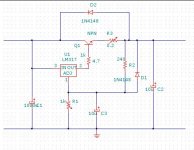
This alim use a LM317. The value for the components are just a guess. You must know the output voltage (as ex. 6,3V), the output current and the input voltage in order to calculate the correct values.
The doc for the LM317 can be found at http://www.national.com/ds/LM/LM117.pdf
The formula to calculate the components are inside the doc, as well as other exemples.
The transistor is to obtain more current and power from this alim. You can even use a darlington, but a simple npn must be sufficient up to current equal to 10 time the maximal current the LM317 can drive, that mean 10 time 1.5A = 15A.
The type is not critical, it must be abble to drive the output current and have enough power dissipation.
Attachments
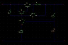
Another circuit only with npn. It is a basic alimentation circuit. The zener is the voltage reference, Q4 compare the voltage on its base with the voltage on its emmiter and drive the output darligton Q1-Q2.
Q3-R1 is the current limitation. Very basic but sufficient. Q3 will conduct when the voltage drop on R1 become ~= to 0.6 volt. It will drive the current from R2 and drop down the base of Q2. This will limit the output current.
As before, you must know the output voltage, the output current and the input voltage in order to calculate the values of the components.
Those 2 circuits are for use with DC only. For AC, a simple way to obtain a current limitation at the start is to use some VDR in the heater circuit. A vdr is a resistor that have a big resistance when cold and a little resistance when hot. It will work with DC too. It can be harder to find a appropriate VDR as to find a few npn or a LM317 or similar.
To use a VDR, you must know the heater current, find a VDR that will support this current, know the voltage drop on the VDR for this current, and calculate the output tension of the secondary of the transformer.
A VDR will only limit the current on the start, but will have almost no effect in case of voltage variations on the primary of the transformer.
Attachments
A few further remarks:
1. My experience over a long time was as Ashok said (#488), that heaters mostly lasted longer than emission life, especially in power tubes. (Depending of course on how often you switch on and off.)
2. Power tubes run below 6,3V will influence maximum available output, but I have used down to 5,3V in pre-amplifiers for slightly lower noise (hiss), i.e. where anode currents of max. 2 - 3 mA were drawn. I have not found ill effects.
3. Hum from ac on heaters - one must also not forget induction into the signal circuit because of the presence of 9Vpeak ac, often at some current, if not carefully wired.
4. Although I have never used it, I will support the advantage of turn-on current limiting despite (1) above.
Regards.
Dominique_free said:
A good way to get a longer life is to limit the current at the start.
With AC, the cause of the hum is the parasitic cap between the filament and the cathode. ...
With DC, the best way for me to do this, is to use a regulator as a LM317 or 7805. If the power of the regulator is not enough, you must put a npn transistor at the output of the regulator.
Dominique_free said:This alim use a LM317...
Dominique_free said:Another circuit only with npn. ...As before, you must know the output voltage, the output current and the input voltage in order to calculate the values of the components.
Those 2 circuits are for use with DC only. For AC, a simple way to obtain a current limitation at the start is to use some VDR in the heater circuit. ...A VDR will only limit the current on the start, but will have almost no effect in case of voltage variations on the primary of the transformer.
Johan Potgieter said:
1. My experience over a long time was as Ashok said (#488), that heaters mostly lasted longer than emission life...
4. Although I have never used it, I will support the advantage of turn-on current limiting despite (1) above.
OK lets get some clarity here....
1. In the 6SL7-6SN7--EL34 amp (wayne's ckt) should we consider only AC for the heaters or use DC for the 6SL7 and maybe even the 6SN7 to reduce hum?
2. If are using both AC and DC wont we need a VDR to limit current on start up for the power tubes and along with a ckt like one posted by Dominique for the 6SL7 and maybe even the 6SN7?
I need to know this as my power tranny depends on this. Presently it is speced to have AC for the EL34 Power tubes and DC for the 6SL7 and 6SN7.
- Status
- Not open for further replies.
- Home
- Amplifiers
- Tubes / Valves
- EL34 schematic confusion