Navin,
If you really need to rectify the heater supply to 6SN7 and 6SL7, I think you'd be better off with a higher voltage than 6.3v for that winding (maybe 9v?) to allow some margin for adding a smoothing network. I understand that poorly smoothed DC supplies for heaters can be a source of noise but I have no experience of doing this, so maybe someone who has experience can comment
What happened to the idea of a 12v winding for relays?
An electrostatic shield between primary and secondary is a good idea.
If you really need to rectify the heater supply to 6SN7 and 6SL7, I think you'd be better off with a higher voltage than 6.3v for that winding (maybe 9v?) to allow some margin for adding a smoothing network.
Yes, to play it safe, 8-9VAC CT with CT to ground, 4 diode bridge -> smoothing cap -> dropping resistor -> smoothing cap -> heaters! BTW I've found that 2) 2200uF caps // are better than 1) 4700uF.
6SL7 300mA + 6SN7 600mA = 900mA
My current amp has two 6U8's = 900mA, same setup as above with a .22 ohm 3W WW dropping resistor from 6.3VAC (A?) to 6.2VDC. Very little heater humm, could be better tho.
And I'd (secondly) highly recommend a shield betwixt the pri-sec, connected to gnd.
Also the HT winding (340V) does not have a CT!
And always place a 10nF/2-3kV ceramic cap across the mains (pwr) switch. Helps to prevent sw contact arcing / welding.
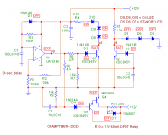
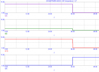
Opamp timer anyone? With LED standby + power on indicators...
Now this is in it's infantcy as I've spent the good part of last night downloading/searching BJT models. In otherwords the BJT's I've used in the sim aren't optimal, YET!
Contact ratings for 450VDC...? Place in gnd path with a 10-15k hi-wattage WW resistor bypass...?
One thing about the fear of heater shock. I've never experienced heater failure from turning the amp on-off. It's almost unheard of!
With fixed bias I don't even fear cathode stripping! If you still want slow turn-on, remember SY suggestion? Those big old (25 inch) tubed Color (Colour for you Brit's!) TV's had them! 😉
Cheers
Wayne
Sorry navin it's 12V, but could be adjusted for 6V but I like 12V better! Hint: 12V relays are cheaper/easier to drive!
Steal a xfrmr from an old clock radio!

Attachments
navin said:
JoJoD818, How do you do this? Since we have similar climes i feel safe copying you.
do you have a switch or do you manually set bias voltages if the ambient temp is below 25 deg C? or is it more complex in that the bias is set via a temperature sensor that senses the ambient and sets the bias automatically?
Also my power tranny guy wanted confirmation on the specs of the power tanny. Since he lives 1500km away and I cant send the power tranny back I'd like to double check..
Primary 230VAC
Secondary:
370V AC CT (370-0-370), 1Amp, additional taps at 340V and 355V
6.3V AC 8A CT (for EL34 heaters)
6.3V AC 4A CT (for 6SL7 and 6Sn heaters) to be rectified to DC
70V AC (no need for CT) 0.2A for bias
Are the above specs ok? Will i need additional windings?
Is there a need for a shield between primary and secondary?
Nothing special navin, I just adjust the bias up when it's cold. 😎
As for your tranny, a 370-0-370 can be used but I think Wayne's schematic only used a 0-370 since he used a bridge diode. Mine has 370-0-370 because it was meant for a ST70 clone project which didn't pushed thru. So for your application, a 0-370, with taps at 340 and 355 should work fine.
Hi Wayne,
Would a simple 555 timer be enough for slow turn-on? Don't get me wrong, your circuit looks good, besides I'm worried about the 555 if it's gonna be a noise problem.
I think of putting a 47K 10W resistor between the diodes and the first cap, then after about 20-30secs, a relay contact shorts out the 47K resistor.
What do you guys think?
Would a simple 555 timer be enough for slow turn-on? Don't get me wrong, your circuit looks good, besides I'm worried about the 555 if it's gonna be a noise problem.
Yeah I know, I've added a lot of bells and whistles to it! 😉 Trying to show off but you could use another chip to replace all those bjt's or an all in one chip! I do stuff like that to practice logic in my one remaining brain cell!
Actually you can almost drive a 60mA relay straight from the op-amp itself, but 1 extra piece of sand (BJT) aka 2SC945, 2SC1815, 2N**** as a buffer/driver/inverter will make it more reliable and easier to implement. Even some unknown npn/pnp piece of plastic in your coffee can will work!
A 555 may introduce noise depending on your gnd'ing etc. I dunno!

I think of putting a 47K 10W resistor between the diodes and the first cap, then after about 20-30secs, a relay contact shorts out the 47K resistor.
Just a guess = maybe! What about arcing and such? Hey I've seen 1A relays melt on 120VAC! Not me, my brother! 😀
So you would need a good one and possibly along with that a higher current coil. Don't you have the pwr tranny w/CT? Then place the relay in the CT! That is if the CT is GND! That way there will be no highish voltage!
Also try a lower value resistor than 47k, seems just a little on the high side to me. I'm thinking a lower value will let the PSU caps charge a little more before you slap it with the full 440V or so. Less in-rush current.
So all those extra BJT's aren't needed, just one will do the buffering/driving!
Cheers everyone
Wayne 🙂
Edit: A DPDT or a DPST will allow you to "double up" on the contacts!
Looks like it's a full featured circuit, besides, practicing logic is really fun.
Anyway, my idea is to run the 555 from a voltage doubler with the unused 5VAC that my tranny has (and yes my tranny has CT on the HT), isolate the 555 supply from ground. Still, the 555 is a clock right, and I don't want any ticking coming out of my amp! But it's simplicity is so tempting. 😱
On the 47K, it's just there so that the caps can charge a bit before the relay shorts it out, woldn't this charge be enough to eliminate any sparks in the relay's contacts? Perhaps a smallish cap to bypass the contacts can also help?
Like you, I really love to practice my brain before I do it for real.
 OT: Speaking of "real", I just bought about 30pcs of 1N4007 from a local shop and hooked it up to my 370-0-370 tranny and to my surprise one of the diodes was smoking!
I checked all the remaining diodes I bought and alas! Found several 1N4002 among them! I feel so stupid because I didn't took the time to double check the part numbers. I should have checked them even if I knew I bought 1n4007s and not 4002s, the clerks could have mixed up their stocks unknowinglly.
Well, no one got hurt, just a sudden jolt of adrenaline I guess. Lesson learned - check the values first before plugging in!
Anyway, my idea is to run the 555 from a voltage doubler with the unused 5VAC that my tranny has (and yes my tranny has CT on the HT), isolate the 555 supply from ground. Still, the 555 is a clock right, and I don't want any ticking coming out of my amp! But it's simplicity is so tempting. 😱
On the 47K, it's just there so that the caps can charge a bit before the relay shorts it out, woldn't this charge be enough to eliminate any sparks in the relay's contacts? Perhaps a smallish cap to bypass the contacts can also help?
Like you, I really love to practice my brain before I do it for real.
OT: Speaking of "real", I just bought about 30pcs of 1N4007 from a local shop and hooked it up to my 370-0-370 tranny and to my surprise one of the diodes was smoking! I checked all the remaining diodes I bought and alas! Found several 1N4002 among them!
I feel so stupid because I didn't took the time to double check the part numbers. I should have checked them even if I knew I bought 1n4007s and not 4002s, the clerks could have mixed up their stocks unknowinglly.Well, no one got hurt, just a sudden jolt of adrenaline I guess. Lesson learned - check the values first before plugging in!
Also try a lower value resistor than 47k, seems just a little on the high side to me.
i thought so too, anyway, time constant RC, would indicate long period. and you still have to switch B+ when filaments are all heated up and stabilised, anywhere from 15 to 30 secs.
normally the resistance presented by the transformer ht winding should limit inrush to input capacitor, so if you want to limit 340volts ht to say 1A then you should have a 340ohm resistance (this includes ht winding dc res plus a series resistor you may want to add)
now a 340 ohm resistance and a 200ufd has a time constant of 0.068 secs so your full ht can come on up in about 250msec.
so if your ht winding has enough dc resistance you may not need a resistor at all.
i am more particular to turning on the B+ after all filaments have stabilised.
you can even use a toggle switch for that, manually turning on B+ after several sec. a time dealy relay is not an absolute nescesity imho.😀
please look at my post #375
i posted a breadboarded 555 timer in post#375, with a 1Meg resistor and a 27ufd tantalum, a delay over 30 secs is achived. and you can see that it is very simple.
circuit is very standard.
Opamp timer anyone?
i posted a breadboarded 555 timer in post#375, with a 1Meg resistor and a 27ufd tantalum, a delay over 30 secs is achived. and you can see that it is very simple.
circuit is very standard.
you can even use a toggle switch for that, manually turning on B+ after several sec. a time dealy relay is not an absolute nescesity imho. 😀
I agree!
And here's your toggle/standby switch!
www.diyaudio.com/forums/showthread.php?postid=826241#post826241
Wayne 😀
i posted a breadboarded 555 timer in post#375, with a 1Meg resistor and a 27ufd tantalum, a delay over 30 secs is achived. and you can see that it is very simple.
Yes it is, two (maybe) resistors simplier. I threw in an opamp timer so anyone who did not have a 555 would not have to go out and buy one! I have a parts drawer full of them. You can do the same bells and whistles with a 555. You know like two LED's, one for power on RED, one for standby YELLOW.
Opamp timer:
1 coffee can opamp
4 resistors max, can get away with 3
1 cap (timing)
1 coffee can diode
1 coffee can transistor
Very simple. Resets almost immediately on power-off. Diode drains timing cap.
Wayne 😉
Simple circuits are very tempting indeed but this circuit may work too. I have tried this for preamps and all but want to try it on an amp. See Figure 5.
http://headwize.com/projects/showfile.php?file=ahammer1_prj.htm
It controls 3 relays in a 40sec, 60sec, 70sec sequencial fashion. The timing can easily be changed too for shorter period.
My idea is once the amp is switched on, only the heaters are powered up, then after 40sec the HT is applied through a current limiting resistor then after 20secs (60sec) the resistor is shorted out applying the full HT, then finally after another 10sec (70sec) the input is unmuted.
😎 or ?
http://headwize.com/projects/showfile.php?file=ahammer1_prj.htm
It controls 3 relays in a 40sec, 60sec, 70sec sequencial fashion. The timing can easily be changed too for shorter period.
My idea is once the amp is switched on, only the heaters are powered up, then after 40sec the HT is applied through a current limiting resistor then after 20secs (60sec) the resistor is shorted out applying the full HT, then finally after another 10sec (70sec) the input is unmuted.
😎 or
?Really, you don't need any high accuracy in the timing; if they go off at 35, 44, and 51 instead of 30, 40, 50, nothing untoward will result. A 555 is already overkill. Try one relay, one transistor, one resistor, and one cap per timer. Oh, yes and an antikickback diode across the relay coil.
SY,
I agree with you, it won't really matter how accurate the timing is, say just about 30 seconds will do. And I must admit your approach is simple and neat. To make it simpler I think the third timer for mute is not neccesary since I be using a volume pot, set to minimum everytime the amp warms up.
Thanks!
navin said:
Secondary:
370V AC CT (370-0-370), 1Amp, additional taps at 340V and 355V
6.3V AC 8A CT (for EL34 heaters)
6.3V AC 4A CT (for 6SL7 and 6Sn heaters) to be rectified to DC
70V AC (no need for CT) 0.2A for bias...
Tony said:if you are using wayne's psu schematics then you won't need a 370-0370 volts, just a staight 370volts with taps at 340volts, otherwise the rest of the specs are good.
You guys ahve been busy! Thanks so much for your support.
Revised Specs.
370V AC, 1Amp, additional taps at 340V and 355V
6.3-0-6.3V AC 8A CT (for EL34 heaters)
9-0-9V AC 2A CT (for 6SL7 and 6SN heaters) to be rectified to DC
70V AC (no need for CT) 0.2A for bias...
12V AC 0.5A for delay ckt and relays
OK??????
ray_moth said:
If you really need to rectify the heater supply to 6SN7 and 6SL7, I think you'd be better off with a higher voltage than 6.3v for that winding (maybe 9v?) to allow some margin for adding a smoothing network.
What happened to the idea of a 12v winding for relays?
An electrostatic shield between primary and secondary is a good idea.
agreed. 9V CT it is and a 12V 0.5A winding has been added to the requirement.
Wow! I sure am glad I did not order the power tranny without confirmation. Thanks again!!!
cogsncogs said:
Yes, to play it safe, 8-9VAC CT with CT to ground...6SL7 300mA + 6SN7 600mA = 900mA
Also the HT winding (340V) does not have a CT!
Opamp timer anyone?...
...Those big old (25 inch) tubed Color (Colour for you Brit's!) TV's had them! 😉
Sorry navin it's 12V..Steal a xfrmr from an old clock radio!
It's ok. I have added a 12V 0.5A winding to the requirement so I have enough to drive the relays.
CT on the HT winding has been droppped. Sorry i did not get that at first.
BTW since I am getting a custom power transformer why steal one from a old clock radio? confused?
thanks for the delay ckt. 0.5A should do to run it along with the relays right?
navin said:
You guys ahve been busy! Thanks so much for your support.
Revised Specs.
370V AC, 1Amp, additional taps at 340V and 355V
6.3-0-6.3V AC 8A CT (for EL34 heaters)
9-0-9V AC 2A CT (for 6SL7 and 6SN heaters) to be rectified to DC
70V AC (no need for CT) 0.2A for bias...
12V AC 0.5A for delay ckt and relays
OK??????
navin,
heaters for EL34 should read 3.15-0-3.15
not 6.3-0-6.3
the rest OK.
SY,
I'm designing a pcb for the ccs, would the MJE340 require a heatsink? 1/4W or 1/2W resistors?
Regards,
JojoD
I'm designing a pcb for the ccs, would the MJE340 require a heatsink? 1/4W or 1/2W resistors?
Regards,
JojoD
navin,
here's as simple as it gets, time delay relay circuit, values are for 3secs delay, just increase the value of the capacitor an series resistor for more delay.
here's as simple as it gets, time delay relay circuit, values are for 3secs delay, just increase the value of the capacitor an series resistor for more delay.
navin said:
Revised Specs.
370V AC, 1Amp, additional taps at 340V and 355V
6.3-0-6.3V AC 8A CT (for EL34 heaters)
9-0-9V AC 2A CT (for 6SL7 and 6SN heaters) to be rectified to DC
70V AC (no need for CT) 0.2A for bias...
12V AC 0.5A for delay ckt and relays
OK??????
JojoD818 said:
heaters for EL34 should read 3.15-0-3.15
Second revision....
370V AC, 1Amp, additional taps at 340V and 355V
3.15-0-3.15 AC 8A CT (for EL34 heaters)
9-0-9V AC 2A CT (for 6SL7 and 6SN heaters) to be rectified to DC
70V AC (no need for CT) 0.2A for bias...
12V AC 0.5A for delay ckt and relays
BTW are the amperages ok?
lastly with reference to the voltages posted here...
http://www.diyaudio.com/forums/attachment.php?s=&postid=823147&stamp=1137872257
I would normally use the 340V tap and only if I need more volts (tube change or supply drop) would I use the 355 or 370V taps right?
- Status
- Not open for further replies.
- Home
- Amplifiers
- Tubes / Valves
- EL34 schematic confusion