Second revision....
370V AC, 1Amp, additional taps at 340V and 355V
3.15-0-3.15 AC 8A CT (for EL34 heaters)
9-0-9V AC 2A CT (for 6SL7 and 6SN heaters) to be rectified to DC
70V AC (no need for CT) 0.2A for bias...
12V AC 0.5A for delay ckt and relays
BTW are the amperages ok?
lastly with reference to the voltages posted here...
http://www.diyaudio.com/forums/atta...tamp=1137872257
I would normally use the 340V tap and only if I need more volts (tube change or supply drop) would I use the 355 or 370V taps right?
looks good!
btw, have you decided how to feed dc to the 6SN7/6SL7 heater? are going full wave rects? then you need 2 x 3amps rectifiers, 1N5402 is good here.
you can start with the 340volt winding first, and then chage it if you need more voltage.
good luck.
😀
Tony said:
btw, have you decided how to feed dc to the 6SN7/6SL7 heater? are going full wave rects? then you need 2 x 3amps rectifiers, 1N5402 is good here.
you can start with the 340volt winding first, and then chage it if you need more voltage.
thanks. Yes I was looking for fullwave rectification but had not decided on the device now i will watch for the 1N5402.
JojoD818 said:SY,
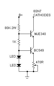
I'm designing a pcb for the ccs, would the MJE340 require a heatsink? 1/4W or 1/2W resistors?
A small floating heatsink is a good idea. You don't want to bolt it to the chassis because of stray capacitance. If you've got voltage to burn, you can always reduce the MJE340 dissipation and get rid of the heat sink by putting a resistor in the collector feed scaled to take up a good proportion of the drop. For example, if you have to drop 80V and are swinging 10V worth of signal, it's quite OK to put in a series resistor calculated to drop 40V at the set current. Resistor... heatsink... your choice.
As for the other resistors... I've got so many things juggling in my head right now that I don't remember your exact impementation. For my Eico's cathode CCS, I use a 2W resistor for the top of the reference string, 1/2W everywhere else.
SY,
Thanks for the answer and tips, btw here's the ccs I'm going to implement.
http://img.photobucket.com/albums/v70/jojod818/Dump/EICOHF87FixedBiasCCS.gif
I'll just put in a small clip-type heatsink for the MJE340 then. I asked so that I can account the heatsink footprint in the pcb.
Thanks,
JojoD
Thanks for the answer and tips, btw here's the ccs I'm going to implement.
http://img.photobucket.com/albums/v70/jojod818/Dump/EICOHF87FixedBiasCCS.gif
I'll just put in a small clip-type heatsink for the MJE340 then. I asked so that I can account the heatsink footprint in the pcb.
Thanks,
JojoD
SY said:Yeah, that's almost exactly what I'm using, 2W resistor and all.
I already have the 3mm red leds you specified (2.4V) but I'm still having trouble finding BC549. What I have access to are BC546, BC182, MPSA06, MPSA42. Can any of these be safely used in place of the BC549?
To be safe, I'll also use 2W for the 1K resistor.
That transistor is totally non-critical. I spec'ed BC549 because of international availability, but any general purpose NPN with highish hfe (100 or higher) and ft (50MHz or higher) will do. In my amp, I'm using an NTE123 because my local shop had 'em.
That's good news, at least I can use what I already have and no need to buy anymore. Just got a couple of 500 ohm Bournes #3309 trimpots for my ccs boards too so it's checklist is complete. Time to finish up on the pcb.
Thank you very much,
JojoD
Thank you very much,
JojoD
JojoD818 said:
I already have the 3mm red leds you specified (2.4V) but I'm still having trouble finding BC549. To be safe, I'll also use 2W for the 1K resistor.
hey i can find BC549 here! See not everything is hard to find in India. 🙂
Re the use of 1N4007 that smoked (post 447): You stated 370 -0-370, so I presume it is the normal full-wave (non-bridge) application, if I understood correctly. In that case the diodes could see 2 x peak voltage in the off-state, or 1046V! (Rated at 1000V). Smoke .... but they could certainly dead-short, with mains variations etc. Was this the explanation?
Regarding dc on heaters: I have experience and can confirm that if the dc is not clean one can very probably get more interference than from ac. By "clean" I do not mean only a large capacitor across - switching transients, etc. From my experience I would certainly not go to this complexity in a power amplifier.
Let us be careful here of meaningless overkill - the old problem of a lot of vague commentary with no quantitave data (I mean in general, not this group). I have built phono pre-amps (sensitivity about 3mV input) with ac on heaters, that with careful layout had negligible hum in the output. For my money the most "complex" arrangement I ever needed was the slider of a pot to earth when best balance was not exactly with a center tap. It was also mentioned that some 15 - 20V positive potential on heaters with respect to cathodes will take care of interference through heater-cathode conduction which some tubes may suffer from.
Hi ,
I strongly recommend the DYNACO Mark II . ( Class AB1 )
It uses two EL34 and one 6AN8 ( a NOS tube easy to find )per channel , it gives 35 Watts RMS per channel , has a insuperable cost / benefit rate .
The sound quality is amazing , and is quite simple to build .
The OT must have 4300 ohms plate to plate with screen-grid taps
at 40 % of total winding .
If you are interested I can send the schematic
Carlos
Johan Potgieter said:
Regarding dc on heaters: I have experience and can confirm that if the dc is not clean one can very probably get more interference than from ac. By "clean" I do not mean only a large capacitor across - switching transients, etc. From my experience I would certainly not go to this complexity in a power amplifier.
Let us be careful here of meaningless overkill - the old problem of a lot of vague commentary with no quantitave data (I mean in general, not this group)..... For my money the most "complex" arrangement I ever needed was the slider of a pot to earth when best balance was not exactly with a center tap. ....
Now I am confused. I was given to understand that the only the 6SL7 really could use DC on the heaters. Now I figured that if I am going to have a seperate 9-0-9V winding to make DC for the 6SL7 why not feed DC to the 2 6SN7s as well.
Each 6SN7 needs 0.6A and each 6SL7 needs 0.15A totalling 1.35A so I figured a 2 Amp 9-0-9V winding would be adequate.
Please correct me.
refference said:Hi ,
I strongly recommend the DYNACO Mark II . ( Class AB1 )
It uses two EL34 and one 6AN8 ( a NOS tube easy to find )per channel ,The OT must have 4300 ohms plate to plate with screen-grid taps
at 40 % of total winding .
Carlos
I appreciate the help. however through great pain and planning i finally am getting the parts (tube parts are rare in India) to build the 6SL7-6SN7 version and I have already got custom 6.6K and 5K OPTs wound for this amp (1 channel triode and 1 channel UL).
It is too late now (for me atleast) to consider another design the other here might be better positioned.
This thread is begining to look like an "EL34 build off". We've covered just about every known version of an EL34 PP Amp. 🙂 LOL
Thanks again.
Johan Potgieter said:Re the use of 1N4007 that smoked (post 447): You stated 370 -0-370, so I presume it is the normal full-wave (non-bridge) application, if I understood correctly. In that case the diodes could see 2 x peak voltage in the off-state, or 1046V! (Rated at 1000V). Smoke .... but they could certainly dead-short, with mains variations etc. Was this the explanation?
Johan,
I used series 4007s and a normal fullwave. It smoked because one of the sections is made up of 4002s intead of 4007s. Simplest explanation was the use of wrong diodes. My mistake.

SY said:There might be an interesting alternative. Hang on a few hours.
I'll surely be waiting. 😀
Thanks!
navin said:
hey i can find BC549 here! See not everything is hard to find in India. 🙂
That's the spirit navin!
I'm trying to build this amp from parts that I already have, a cost-effective way of putting my "junk" stuff into good use I guess. 😀 Just doing it slowly while digging through piles of stock parts and enjoying the work! 😀
JojoD818 said:
I'm trying to build this amp from parts that I already have, a cost-effective way of putting my "junk" stuff into good use I guess. 😀 Just doing it slowly while digging through piles of stock parts and enjoying the work! 😀
I dont have a parts bin. I soruce and buy what i need and trash all the junk after i finish a project.
- Status
- Not open for further replies.
- Home
- Amplifiers
- Tubes / Valves
- EL34 schematic confusion