ray_moth said:In my all-differential design, I use a step network between 6SL7 LTP splitter and 6SN7 differential driver, instead of direct
coupling. This is where my design diverges a little from that of Thorsten Loesh.
The advantages of a step network over direct doupling include:
* A much lower grid voltage on the 6SN7 (could be 50v or less), allowing more suitable operating points to be used for both
6SL7 and 6SN7, in terms of plate load resistor, plate-cathode voltage and plate current.
* Amplification of any DC imbalance in the 6SL7 is much less. DC coupling can cause a serious DC offset.
The coupling capacitor in a step network can be included in a NFB loop without incurring LF instability, which is the most common
objective of using DC coupling in the first place.
The downside of a step network approach, of course, is the cost of a few additional components, namely, 2 grid "leak" resistors, 2 coupling capacitors and two coupling bypass resistors - not a big price to pay, IMHO, for considerably easier design and superior balance.
hi, interesting theory, can you point out to links where i can find more disscussions about these? thanks
navin said:
I was gonna use a poewr supply you posted on a related thread on EL34. see below
wayne, no news if you thiink your power supply posted above will work with the EL34 schematic.
ray moth, I am not very worried about a little crosstalk. it might even be desireable given that the same 6SL7 will be be to drive a triode amp and a UL amp of the smae channel.
Right, Navin, I didn't even think of that (duuhhh!). Crosstalk is indeed a non-issue in that case.
On the subject of pwr tranny's IMO a good secondary set up would be:
1) 370VAC HT w/ taps @10 or 15V apart, say 340, 350, 360 etc.
340-350VAC approx. is what you will need, depending on how much current you will be pulling from it and the source impedance of the tranny. This is where Duncan's PSUD comes in handy. So you will need to figure this out before you order. I have no idea what the source imp. of my tranny is, but it is rated @500mA. One big pwr tranny!
2) 6.3VAC CT for EL34 heaters (mine has no CT)
1) 6.3VAC CT for Input/Driver heaters (I run mine DC)
1) 60-70VAC for output tube bias
Some regulate the bias supply when they shouldn't. One good reason not to is that the bias supply will follow the HT supply, say during mains supply fluctuation. The only time to regulate the bias supply is if the HT is regulated also, esp. the screen supply when operated in 'pentode' mode.
IMO I would say it's best to over-design the power supply a little! This is an area where a lot of manufactures 'skimp', go the cheap route and turn an otherwise good amplifier design into a bad one!
So a little over-kill here is a good thing!
navin, this is a very good recomendation! it is wise to have taps on your ht winding since the power situation in your area is not so good.
Tony said:
thanks, and i thought these miniatures are an improvement as far as space reduction is concerned without giving away sonic qualities, but then its just me.
Tony, no. It is not just you. My sentence about shock and microphony may have appeared ambiguous: Miniatures are an improvement there, also somewhat improved heat conduction to the outside via the short pins. and space. (The latter of minimal significance though in power amplifiers reference the size of the rest.)
Tony said:
navin, this is a very good recomendation! it is wise to have taps on your ht winding since the power situation in your area is not so good.
I downloaded the software from duncan labs but how does one really use it?
cogsncogs said:
1) 370VAC HT w/ taps @10 or 15V apart, say 340, 350, 360 etc.
340-350VAC approx. is what you will need, depending on how much current you will be pulling from it and the source impedance of the tranny. This is where Duncan's PSUD comes in handy. So you will need to figure this out before you order. I have no idea what the source imp. of my tranny is, but it is rated @500mA. One big pwr tranny!
2) 6.3VAC CT for EL34 heaters (mine has no CT)
1) 6.3VAC CT for Input/Driver heaters (I run mine DC)
1) 60-70VAC for output tube bias
cant we just have the following....
370V CT 1A with tap at 340V
6.3V CT 10A for all 7 heaters (EL34, 6SN7 and 6SL7)
70V AC 0.2A for output tube bias
and use this ckt replacing C11 with 2 x 220uf / 250V?
http://www.diyaudio.com/forums/attachment.php?s=&postid=823147&stamp=1137872257
voltage fluctuations can be managed by using an external CVT/Stabiliser.
cant we just have the following....
370V CT 1A with tap at 340V
6.3V CT 10A for all 7 heaters (EL34, 6SN7 and 6SL7)
70V AC 0.2A for output tube bias
and use this ckt replacing C11 with 2 x 220uf / 250V?
http://www.diyaudio.com/forums/atta...tamp=1137872257
voltage fluctuations can be managed by using an external CVT/Stabiliser.
hey navin, its your amp, you can do it the way it pleases you, although some safety considerations have to be observed.
C11 can be 2 x 0.22ufd/250 or 450 volts film caps, i believe we have discussed this earlier, otherwise the circuit is fine to use as is. if you were near my house i'd gladly give you a cap or two.😀
For me, microphony have much more to do with tube quality as with tube type. I have mesured the microphony and the intrinseq noise of 10 different brands of ECC83, a few 6SN7, ECC81, ECC82 and E188CC. What appear to me was 2 things:
1) With many tubes, in general but not always the cheaper, it is an inverse relation between the noise and the microphony: more intrinseq noise implies less microphony. As the noise is very important in regard to the sound, the sound was better with tubes in this category having more microphony and less noise.
2) It is a few tubes with very little noise and microphony. They have the best sound of all. The special quality tubes as E88CC are always in this category. For the other types, if not sure, you must try and test a few brands in order to find the better ones.
After that, I get better overall result with tubes as ECC83 as with 6SN7, especially in the first stage of the pre-amplifier. It is this stage that will determine the most of the noise of the whole amplifier, and for the other stages, it doesn't matter much, in respect to noise and microphony, which type of tubes is used.
I am doing most guitar amplifiers without any feedback, so it can vary with a hifi amplifier. The advantage of an ecc83 is at I will archieve a very high voltage gain in the pre-amplifier, it is great if you want to sature the whole pre-amplifier with the guitar.
But in an hifi amplifier, it can be better to use tubes with less gain, in order to be able to use less feedback. It another advantage with using low gain tubes, it is easier to get a large frequency response with such tubes. Feedback is good to stabilise the gain of an amplifier, but not to get the frequency response.
Tony said:
hey navin, its your amp, you can do it the way it pleases you, although some safety considerations have to be observed.
C11 can be 2 x 0.22ufd/250 or 450 volts film caps, i believe we have discussed this earlier, otherwise the circuit is fine to use as is. if you were near my house i'd gladly give you a cap or two.😀
Safety? what safety? it's only 500VDC! 🙂 Just kidding.
I like to have those with more knowledge than me to qualify my decisions.
I dont see much of an advantage of having too many taps on a transformer (340 and 370 should be adequate) as i wont be changing taps as an when the mains fluctuates. The only reason to have the 370V tap to me would be to allow the amp to accomodate larger tubes (KT88, 6550) in the future.
I am looking at building my amp in a 12" square x 2-3" high chassis. I hope to have a scanned sketch of the layout up sometime tomorrow morning (Indian time).
I dont see much of an advantage of having too many taps on a transformer (340 and 370 should be adequate) as i wont be changing taps as an when the mains fluctuates.
No, I was mainly concerned about the load regulation of the pwr tranny. And the mains voltage being off slightly on somewhat permanent basis, not on a daily basis. When I first moved to where I am now my mains voltage was 108-110V for two years. Now for the last 8 years it's at where it should be, 120-125V, after an old substation blew in a storm! The main reason for multiple taps on the secondary will allow you to compensate for any design flaws (bad/not so good regulation) of your tranny!
And not only multiple taps on the secondary but the primary as well is a very good idea. A good choice for a single winding for the output stage would be 6.3VAC CT @8A.
Plus a separate winding for the heaters for the input/driver stages will allow you the run them with DC at a later time if you wanted to. And keep them electrically isolated from the output stage, whether AC or DC. 😉
In your situation the only tube that I would consider running the heaters on DC would be the 6SL7 as this is where most of the gain occurs and would be amplified by the following stages.
And really it is not that much more complicated or expensive to do so! 4) rectifiers, 2) caps, and a resistor!
voltage fluctuations can be managed by using an external CVT/Stabiliser.
How much does one of these cost? 😀
340V to 370V is too big of a jump. A 42VDC jump! OK maybe taps @ 340V, 350V or 355V. (1.41*340 = 479.4, 1.41*350 = 493.5) at no load. But your secondary output voltage will be higher w/no load, depending on the load regulation of your tranny.
Your B+ (HT) is somewhat critical as it will determine your power output, bias setting, plate dissipation, optimum OPT primary imp., voltage rating of the PS caps. The DC output voltage will depend on the secondary DC winding resistance (source impedance, load regulation!) and the load attached to it. As can be seen you will need (best) a pwr tranny with good load regulation, esp a class AB amp.
So in other words if your custom wound pwr tranny has good load regulation, 340-350VAC you will come out OK!
The only reason to have the 370V tap to me would be to allow the amp to accommodate larger tubes (KT88, 6550) in the future.
You will have (you should, I would!) to upgrade your PS capacitors to 350V units if you go up to 370VAC as you will be close to 500VDC (522V or higher on start up) B+. And I and others don't like running our 'lytics so close to the maximum Working Voltage (WV)!
and use this ckt replacing C11 with 2 x 220uf / 250V?
I think you mean 2x .22uf (220nF)? Well you could but the ESR will get in the way of the purpose of this cap. This cap is placed as close as possible to bridge rectifier to help in the reduction of diode switching noise. 630V is non-negotionable! I'd recommend a tin & foil polypropylene, not a metalized cap if possible!
Not shown in the schematic is a 10nF, .01uF/2-3kV hi-voltage ceramic cap connected across the HV secondary. This is a 'snubber cap'. Very helpful in reducing diode switching noise, heat build-up in the pwr tranny (amazing!) and transformer buzz! And will make a large improvement in the sound of your amp! I have one of those across every secondary that is being rectified! Also placed at strategic points from signal gnd to chassis gnd.
Hopes this makes good sense to you, I'm only trying to help and give some food for thought! 😉 😀
Wayne 😎
Dominique_free,
You posted valuable experience (#409); may I add some comment, more to enlarge than to differ, for benefit of newer members in audio. (Some of this have already been given on other threads; regular members would bear with me.)
Firstly it is a pity that modern tube quality is so inconsistent; yes, one must constantly test.
With regard to noise I agree that it is important in that it is always there, whereas microphony is only a problem when a very high sound level impinges on an amplifier or if it is unrigidly mounted and prone to shock, bumps, whatever. But there is not a simple direct relationship between noise (electronic) and microphony. E.g. it is expected that the large construction of a 6SL7/6SN7 is more prone to vibration than a small rigid construction like an ECC88, irrespective of emission noise, or special rigid construction like some ECC83s for audio. But because microphony mostly relates to movement of the grid with respect to the cathode, i.e. it is amplified and there comes in the MU of the tube. In practice this may largely agree with what you found.
The purpose in high fidelity is primarily low distortion; in that sense the frequency response is secondary (one excludes filter circuits). In fact, in any good design the frequency response before any feedback should be the whole audio spectrum so as to have effective feedback at all frequencies. In such designs frequency response after feedback will naturally be far wider than needed. Lower gain triodes (including low Rp) will normally be better than high gain ones, but then pentodes can have still higher gain with wide frequency response and low input capacitance. (Folks frown on pentode noise - in feedbackless circuits such as perhaps your guitar amplifiers that can be a factor, but I have never found pentode noise much of a bother especially with feedback, unless one listens right inside the loudspeaker.)
And always the basic rule which has been often stated: Feedback is only a problem in mediocre designs, where too much is applied injudiciously to try to clear things up. Design a good amplifier before feedback and only a moderate amount (say 20 dB) will be required to make it excellent.
A little off-thread but hopefully useful for some in addition to your findings.
the reason i brought up the subject of the octals versus the miniatures here is because Navin is attempting to build an EL34pp amp using the 6SL7/6SN7 as front end tubes. and i would like to get your opinions as to the use of the 12AT7/6FQ7/6CG7 alternative.
these octals are hyped to be the "tubes to use" in some forums, but i would like to go beyond that and try to get more meat out of this.
these octals are hyped to be the "tubes to use" in some forums, but i would like to go beyond that and try to get more meat out of this.
navin,
What Wayne said is the "safe" way of designing your psu. Better prep your psu for 1) safety against fluctuations, or other nasty voltage spikes and 2) for future tube upgrades.
That way, you'll have a universal type psu and just by tapping the secondary to a different tap you can use different output tubes.
cogsncogs said:
No, I was mainly concerned about the load regulation of the pwr tranny. And the mains voltage being off slightly on somewhat permanent basis, not on a daily basis. When I first moved to where I am now my mains voltage was 108-110V for two years.
And not only multiple taps on the secondary but the primary as well is a very good idea. A good choice for a single winding for the output stage would be 6.3VAC CT @8A.
Plus a separate winding for the heaters for the input/driver stages will allow you the run them with DC at a later time if you wanted to. And keep them electrically isolated from the output stage, whether AC or DC. 😉
In your situation the only tube that I would consider running the heaters on DC would be the 6SL7 as this is where most of the gain occurs and would be amplified by the following stages.
And really it is not that much more complicated or expensive to do so! 4) rectifiers, 2) caps, and a resistor!
How much does one of these cost? 😀
340V to 370V is too big of a jump. A 42VDC jump! OK maybe taps @ 340V, 350V or 355V....So in other words if your custom wound pwr tranny has good load regulation, 340-350VAC you will come out OK!
You will have (you should, I would!) to upgrade your PS capacitors to 350V units if you go up to 370VAC as you will be close to 500VDC (522V or higher on start up) B+. And I and others don't like running our 'lytics so close to the maximum Working Voltage (WV)!
I think you mean 2x .22uf (220nF)?.... 630V is non-negotionable!
I'd recommend a tin & foil polypropylene, not a metalized cap if possible!
Not shown in the schematic is a 10nF, .01uF/2-3kV hi-voltage ceramic cap connected across the HV secondary. This is a 'snubber cap'.
Hopes this makes good sense to you, I'm only trying to help and give some food for thought! 😉 😀
Wayne 😎
Much appreciate all the help you have given me. I plan to base my power supply on the one you posted on another thread.
Power where I live is not always low. It fluctuates between 170V and 300V sometimes in minutes. To protect our gadgets we a have 1.5KVA UPS like these in every room...for telephones, PCs, routers and other small signal stuff.
http://www.apc.com/resource/include/techspec_index.cfm?base_sku=BR1500-IN
My exisiting stereo is run of 2 CVTs the power amp has a 3KVA CVT and the rest of the electronics share a 1KVA CVT.
With this in mind 2 taps of 340V and 355V should be ok right?
So you prefer that there be 2 6.3V taps one that can be converted to DC and one to be used for AC.
One tap will be 6.3V 8A and the other 6.3V 2A with DC on for the 6SL7 heater. What if I run all heaters in DC? What are the advantages and disadvantages other than a 10A DC rectifier.
The only reason I suggested lower volt caps is that 630V is not available locally.
The snubber (10nF 3KV) cap is connected across the HV secondary output? That means AC? Any alternate given that we dont find even 630V locally.
Thanks. I really appreciate all the time and energy you have devoted to helping me.
BTW I plan to source my Power tranny from here. http://www.toroidal.com/a1_main.htm
Tony said:the reason i brought up the subject of the octals versus the miniatures here is because Navin is attempting to build an EL34pp amp using the 6SL7/6SN7 as front end tubes..
Octals sure look more impressive! 🙂 in fact as far as aesthetics go i am gonna try and make the amp look like it was built in 1960 but extrmely well maintained.
JojoD818 said:
What Wayne said is the "safe" way of designing your psu.
That way, you'll have a universal type psu and just by tapping the secondary to a different tap you can use different output tubes.
Agreed. I would like to expriment with KT88 and 6550 once this amp is done.
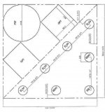
The attached is my left channel amp layout.
The OPT with the dimensions given is the rear of the box and the right side of the box is that side where the diameter of the 6SN7 is shown.
Object:
1.To keep the Power supply as far from the 6SL7 as possible.
2. Not make the chassis too large (under 150 sq. in if possible)
3. Enough room around the 6SL7 as it has over 15 passive components attached to it (for 2 channels)
I looked at many layouts and liked various features of each then figured that the Power supply would have greast interferance when the signal level was low.
Q1: Is the distance between the OPT and the EL34 too small
Q2: Is the distance between the PS tranny and OPT too small
Q3: Any preference with which OPT should be wired in Triode and which in UL?
If this looks ok I would consider making a mirror image of this for the right channel.
Attachments
I have never used a pentode in a preamplifier for my guitar amps. I have recently try a cascode montage, but I must do more test on it. For now, the sound is excellent with clear sounds, but not as good as with a common cathode when I get in saturation. I will maybe make 2 preamps as in some commercial guitar amps.Johan Potgieter said:Folks frown on pentode noise - in feedbackless circuits such as perhaps your guitar amplifiers that can be a factor, but I have never found pentode noise much of a bother especially with feedback, unless one listens right inside the loudspeaker.
And always the basic rule which has been often stated: Feedback is only a problem in mediocre designs, where too much is applied injudiciously to try to clear things up. Design a good amplifier before feedback and only a moderate amount (say 20 dB) will be required to make it excellent.
I have some experience with the repair of old hifi amps. A good practice to me is to recalculate the frequency band of all the stages, and change the condensators in respect to the result of the calculation. Many manufacturers spare money on condensators, and the result is a sound that is not as good as it could be in the bass.
SY, Wayne,
Just got hold of pairs of 45, 100, and 350 ohms thermistors. My tranny has 340-0-340 (with taps every 10 volts up to 370V) and I plan to use fullwave ss diodes.
Where is the best place for me to put the thermistors? Between the tranny and diodes? My psu is undergoing experiments, so anything is possible.
Thanks!
navin,
your layout looks very good for me. the spacings are more than adequate for the EL34 or maybe KT88.
the 12"x12" is just one channel right?
your layout looks very good for me. the spacings are more than adequate for the EL34 or maybe KT88.
the 12"x12" is just one channel right?
- Status
- Not open for further replies.
- Home
- Amplifiers
- Tubes / Valves
- EL34 schematic confusion