Well it’s too late about the tapped secondary, but oh well I guess. If I have issues I can probably pick up something else. How would I go about measuring its frequency response?
Baudouin0 posted this in my mullard 5-20 thread for testing my transformer. 4.7K resistor inline on the primary from a signal generator. 8R resistor on the secondary tap. Measure in vs out time difference on scope along with signal level.
This is what I plotted for my Sowter UA21. Phase calculated from the time difference between the two traces measured in micro seconds.
Attachments
baudouin0,
The only three ways the output tube will cause fixed bias voltage to drop:
1. If the drive voltage is large enough to cause output tube grid current (g1).
2. If the output tube is faulty and g1 is drawing grid current due to a gassy or leaky tube.
3. A tapped bias winding from the B+ winding that powers the negative bias.
That is all according to the change in total B+ current draw at signal peaks, and the resultant bias tap voltage change with the change in current draw times the DCR of that portion of the winding.
Last edited:
Interesting.
So EL34 350V plate&screen -30V grid = 32ma plate 4.5ma screen.
EL34 367.5V -30V grid = 43ma 6ma
EL34 367.5V -31.5V grid = 34ma 5ma
So you are right not regulating the -g1 voltage actually protects you from mains voltages variation. In fact it nearly cancels.
So EL34 350V plate&screen -30V grid = 32ma plate 4.5ma screen.
EL34 367.5V -30V grid = 43ma 6ma
EL34 367.5V -31.5V grid = 34ma 5ma
So you are right not regulating the -g1 voltage actually protects you from mains voltages variation. In fact it nearly cancels.
Another reasoning.
Tube gets older and grid leak goes up and so does the current.
More current, the supply goes down = less grid voltage = current goes up = supply goes down = less grid voltage = current goes up = ... 😀
Mona
Tube gets older and grid leak goes up and so does the current.
More current, the supply goes down = less grid voltage = current goes up = supply goes down = less grid voltage = current goes up = ... 😀
Mona
Okay, I really haven't been following. Should I use fixed bias like is shown on the Valve-Wizard site? Or should I use cathode bias resistors on each power tube?
Oh don't worry about our little debate about regulation. There's pros and cons of both. Big amp - fixed bias, small amp - cathode bias. As for the the best answer well there is not one. I prefer fixed bias just because you can get more output power and the bias does not sag and produce crossover distortion when near max output. However its harder on the tubes if driven hard and requires two adjustment pots. The grid leak resistors need to be lower to prevent thermal runaway which makes the driver more difficult. It needs a negative supply. However its the best in performance.
Last edited:
Okay, sounds good. I'll try a couple of different designs. For one thing, I don't think this amp will get used all the time, nor will it be driven super hard, so I think I can probably get away with fixed bias. I'll start working on a schematic.
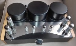
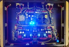
I have build two of this. Very good sounding tube amplifier.😀
Regards Alex
Regards Alex
Attachments

Last edited:
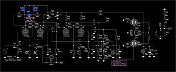
At what bias voltage are those EL34s on your 500V supply Alex?
What is the OPT primary impedance?
What is the OPT primary impedance?
 Since you have a negative rail use it for both CCS. Just use a single 6v8 zener from the negative rail to the both bases - emitter through resistor for each to set the current to the negative rail and a 100v device and your sorted.
Last edited:
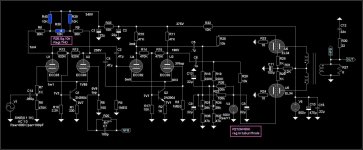
Okay, this is what I have so far, which is power tubes and a phase splitter.
B+1 is 450v, B+2 is 400v, B+3 is TBD
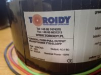
Please look over this and see if you see anything egregious. The transformer shown is an Antek 350v 200VA toroid. The secondaries (350 and 6.3) are both connected in parallel, the primaries as well for 120v mains.
I still need to design the bias supply. I might also go with cathode bias, but 820 ohm cathode resistors seem to be on the high side for cathode bias, because if I understand correctly the higher the value the more bias fluctuation you would get, and the larger the bypass cap would need to be.
Thanks!
View attachment Temp EL34 Amp Schematic.pdf
B+1 is 450v, B+2 is 400v, B+3 is TBD
Please look over this and see if you see anything egregious. The transformer shown is an Antek 350v 200VA toroid. The secondaries (350 and 6.3) are both connected in parallel, the primaries as well for 120v mains.
I still need to design the bias supply. I might also go with cathode bias, but 820 ohm cathode resistors seem to be on the high side for cathode bias, because if I understand correctly the higher the value the more bias fluctuation you would get, and the larger the bypass cap would need to be.
Thanks!
View attachment Temp EL34 Amp Schematic.pdf
IlikeTech,
Your Post # 96 Schematic:
The phase splitter does not have a true current sink in the cathode circuit.
But, the phase splitter plate loads are the same resistance.
That means the phase splitter creates 2nd Harmonic Distortion, which the balanced push pull output stage will not/can not cancel.
A Push Pull output stage only cancels its own 2nd Harmonic Distortion.
It does not cancel the 2nd Harmonic that is sent to it from an earlier stage (in this case the phase splitter).
You forgot to connect a resistor, Rg1 to ground at the input, 6SN7 pin 4, and forgot to connect a signal to that grid.
And you may want to use grid stoppers in series with each grid of the phase invertor to the other circuitry.
Your output stage is using 10 Ohm cathode resistors. And, it is using fixed bias (Adjustable?). You need to use very well matched output tubes.
Or, used individual self bias resistors and individual bypass caps, and ground the g1 resistors instead of connecting them to the fixed bias.
The phase splitter uses a cathode resistor that is what makes it split the phase (the 8.2k Ohm "self bias" you were talking about?).
You either need a very high resistance there and a negative supply voltage,
Or, better yet a solid state current sink.
Last edited:
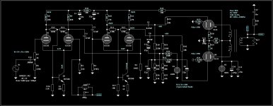
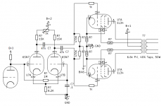
Simple solution 🙂
Grid stoppers for a 6SN7, I think it's not needed.
Coupling capacitors 10n are to small , take 47n.
Mona
Grid stoppers for a 6SN7, I think it's not needed.
Coupling capacitors 10n are to small , take 47n.
Mona
Attachments
Last edited:
Mona,
Good solution to eliminate needing a negative supply!
But the 6SN7 grids are tied together, and the 6SN7 cathodes are tied together.
If the 6SN7 does oscillate, then use grid stoppers (and yes, oscillations have happened).
Parasitics due to the wiring can cause that.
Again, use well matched output tubes, because push output transformers do not like un-balanced DC in the primary.
Or, individual adjustable fixed bias,
Or, individual self bias.
470k and 0.1uF is -3dB @3.4Hz, - 1 dB @ 6.8Hz.
But the recovery time from blocking is relatively quick.
470k and 0.47uF frequency roll off is 4.7 times lower frequency;
But the recovery time from blocking is relatively long.
Of course if negative feedback is employed, the 0.1uF might cause a problem, because of the other low frequency effects, particularly the output transformer.
Eliminate blocking altogether, turn the volume down a little (do not draw grid current).
Tradeoffs, tradeoffs.
Last edited:
With a transconductance of only ~2,5mA/V the risk is minimal but yes, better safe then sorry.But the 6SN7 grids are tied together, and the 6SN7 cathodes are tied together.
If the 6SN7 does oscillate, then use grid stoppers (and yes, oscillations have happened).
Parasitics due to the wiring can cause that.
Or a mix, half self bias and the rest fixed.Again, use well matched output tubes, because push output transformers do not like un-balanced DC in the primary.
Or, individual adjustable fixed bias,
Or, individual self bias.
The TS proposed only 10n , -3dB @ 34Hz, so I would put 47n as a good compromise.470k and 0.1uF is -3dB @3.4Hz, - 1 dB @ 6.8Hz.
But the recovery time from blocking is relatively quick.
470k and 0.47uF frequency roll off is 4.7 times lower frequency;
But the recovery time from blocking is relatively long.
Of course if negative feedback is employed, the 0.1uF might cause a problem, because of the other low frequency effects, particularly the output transformer.
Or put a DC connected cathode follower in front of the finals.Eliminate blocking altogether, turn the volume down a little (do not draw grid current).
Mona
- Home
- Amplifiers
- Tubes / Valves
- EL34 Push Pull Amp Design