The cathodyne is perfectly valid, however, it has no gain of its own, unlike the LTP. Some output tubes require more drive than others, and the cathodyne can be a bit limited in this regard. That said, Dynaco, Heathkit and many others successfully used it to drive EL34s.
My favorite option does use a little bit of sand (silicon) in it. Personally, having played with a few different topologies I really like the LTP with equal value plate resistors and a CCS on the tail. The IXCP 10M45S is a pretty neat part, though I've also just used a couple of 2SC3503s. IXYS also makes some pretty nice high-voltage depletion mode FETs that would work nicely in this application.
Two other good schematics to look at are the Harman-Kardon Citation V and Citation II. The Citation V is a really, really well-implemented Mullard topology. The Citation II is worth studying as an academic exercise.
Hmm okay, sounds good to me. I'll look at the Citation schematics, and do some more research on phase splitters. I guess I'd better get on ordering that transformer, as it's gonna take a while. What are Edcor's times like lately, anyone know?
Thanks!
Thanks!
For a driver, what do people recommend? I was thinking about using a pair of 6SN7s, one as a gain stage and cathodyne and the second one as the drivers. Seem reasonable? I guess I'll figure out if I need more gain as I go.
Is there an advantage to using a small signal pentode for the gain, or is that just to get a lot of gain with 1 tube?
Thanks!
Is there an advantage to using a small signal pentode for the gain, or is that just to get a lot of gain with 1 tube?
Thanks!
With pentodes you get lots more gain from a single stage, lower input capacitance and sometimes more drive capability, though that last point is a moot point if there's a light load after the input. Such as a phase splitter. It does matter, though, in two stage SE amps.
I've built a few PP now with pentode inputs, and I quite like a simple input/phase splitter made with a single pentode/triode, like an ECF82/6U8.
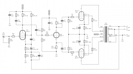
Here's one I built last year as a practice piece. The schematic had to fit in an existing chassis with it's existing transformers, so I had only three tube sockets to populate. Granted, this isn't the most technically perfect example of an EL34 amp, but it works, puts out about 25W (over 30W at clipping). But distortion is stupidly high, hitting 1,2% at specified power. It does sound kind of sweet, though.
I've built a few PP now with pentode inputs, and I quite like a simple input/phase splitter made with a single pentode/triode, like an ECF82/6U8.
Here's one I built last year as a practice piece. The schematic had to fit in an existing chassis with it's existing transformers, so I had only three tube sockets to populate. Granted, this isn't the most technically perfect example of an EL34 amp, but it works, puts out about 25W (over 30W at clipping). But distortion is stupidly high, hitting 1,2% at specified power. It does sound kind of sweet, though.
Attachments
Ooh, that's an interesting design. I've got a lot of NOS 6U8s, but I think I'll stick with something I'm more familiar with, and that being triode gain stages. Thanks for the information on small signal pentodes though!
Post # 44 schematic is interesting.
If you change the 6U8 to a 7199; change from individual self bias R and C to non-individual fixed bias; DC couple from the pentode to the concertina grid; and add a low capacitance pF cap from the bottom EL34 Screen to the input cathode feed back node . . .
What do you have?
You have a Dyna Stereo 70.
Look it up, you will see the almost exact same circuit.
And if I still had a Dyna Stereo 70, I would change from non-individual fixed bias, to individual self bias, just like the one in Post # 44
Because 7199 tubes were so expensive and almost "Un-Obtanium", there were those people who replaced it with the 6U8. A few changes in resistance, and perhaps the tube pin-out connections, and you were ready to go.
I loved my Dyna Stereo 70.
Last edited:
I gave that design the name PP/34 Stetson, since I pulled it out of my hat. Or my @rse, to be honest. I came up with this design quickly when I was offered a pair of amps useless to me in their inherent form, but saw that I could do something new (to me) with the iron present there. Even if it was just an excercise. I think I concocted that schematic in a day or two. It does combine elements from many previous designs, though.
The individual bias resistors come from Mullard recommendations. That front end is one I designed previously for an EL84 PP, just slightly beefed up. I do have some 7199 tubes, but didn't want to use them here. Now that I've found where I stashed my bunch of ECF804s I would've probably used those instead of 6U8, given the higher transconduntance of it's pentode side, but back then I couldn't locate them.
But still I think a simple driving stage like that is a little too weak for larger pentodes. A cathodyne splitter is OK for a little power pentode like an EL84, but an EL34 requires more. I've a working but not yet complete KT66 PP prototype with a pentode input and an LTP splitter, and that makes 35W with >0.1% THD given good output tubes. It is a fixed bias design, though, which generally gives more power given the same B+. But still, the difference in THD is in the decade department, and that is noticeable.
However, this simple design does work, and it isn't stupidly expensive to build. And it does sound quite nice. It does require an active preamplifier, however. It uses Hammond 1650F output transformers, and any JTM45-style power transformer should work in this monoblock form. What should be noted is that this schematic has been compensated for that exact transformer, and thus stability with any other iron is suspect. I took great care making it stable.
Ooh, that's an interesting design. I've got a lot of NOS 6U8s, but I think I'll stick with something I'm more familiar with, and that being triode gain stages. Thanks for the information on small signal pentodes though!
Don't be afraid of pentodes. They can be quite lovely when used as what they are; pentodes. I used to think that they have nothing to do with quality audio. But then I heard a pentode input amp designed by a local "guru". Probably the "fastest" and most "liquid" sound I had heard ever. How much of that sound was due to the pentodes, I can't say. But used properly they do have their place in audio. I actually think they've been under utilised for at least the last two decades.
The Dyna Stereo 70, like many amplifiers is not perfect.
But it is an example of positive synergy.
It works better than it should.
Engineers look at a Bumble Bee, and say it can not fly.
The Bumble Bee looks at the Engineer, and says: "Watch Me".
For every engineering problem, there are 100 solutions, of which at least 3 will actually work . . .
but only if all the details are implemented properly.
I think that the mystery of the bumble bee had already been solved (had something to do with different wing angles between up and down strokes, IIRC), but let's not ruin good stories with facts for now.
But one thing I set to solve for myself was output tube balance with cathode biased output stages. I had been taught that current imbalance would bugger the output transformer, so I thought that you'd always need either balanced tube sets or some mechanism to put them into balance. So, after building this amp, I popped a completely differing pair of output tubes on it: a Mullard XF4 EL34 and a Psvane EL34 (completely over-hyped chinesium, if you ask me). And lo and behold, the current imbalance was below 0.5mA. Took the stress out of that one...
But one thing I set to solve for myself was output tube balance with cathode biased output stages. I had been taught that current imbalance would bugger the output transformer, so I thought that you'd always need either balanced tube sets or some mechanism to put them into balance. So, after building this amp, I popped a completely differing pair of output tubes on it: a Mullard XF4 EL34 and a Psvane EL34 (completely over-hyped chinesium, if you ask me). And lo and behold, the current imbalance was below 0.5mA. Took the stress out of that one...
Adolf,
Yes, engineers keep learning.
The Bumble Bee story is merely that, a lesson for some.
I agree with you; individual self bias has many advantages (and as others will point out many disadvantages).
I prefer individual self bias.
Normally, global negative feedback covers many imperfections in an amplifier.
But if anybody would like a lesson in OPT core saturation, take a look at the original Instruction Manual for the Heath Kit W5 amplifier.
At the very bottom pages, there is a graph showing the rise in harmonic distortion at 20Hz and at 100Hz versus the un-balanced current in the output tubes.
The distortion is quite high at small differences in push quiescent current and pull quiescent current, even though the global negative feedback is in operation.
It is very revealing!
Tradeoffs . . .
Last edited:
Output transformer has been ordered! Now to order the rest of what I need and to wait for 6-8 weeks.
For Octal sockets, should I get the ceramic or phenolic ones from eBay?
Thanks!
For Octal sockets, should I get the ceramic or phenolic ones from eBay?
Thanks!
what i dislike about upping the power output on a pair of el34 is that you are forced to use higher anode to anode loads, and for opt's, not so good a prospect, making an 11k a2a to 8 ohm speaker...
a pair of 4d32 will give you 120 watts at 3k a2a and at that impedance, design and building an opt is much simpler..
a pair of 4d32 will give you 120 watts at 3k a2a and at that impedance, design and building an opt is much simpler..
i am fond of the Cinch octal sockets, surplus sales of nebraska should have those....
over here, we get them from torn down tube equipment..
over here, we get them from torn down tube equipment..
octal sockets....Cinch...https://www.surplussales.com/Images/TubeSockets-Accessories/Sockets/tua-ts101p01-eby_thumb.png
(TUA) TS101P01-EBY
EBY classic octal socket. 8 pin. Bakelite. Cadmium plated frame. 1.105" mounting hole, 1-1/2" c-c. 4 round lugs, tie points.
lot's to choose from, Cinch is further scroll down...
(TUA) TS101P01-EBY
EBY classic octal socket. 8 pin. Bakelite. Cadmium plated frame. 1.105" mounting hole, 1-1/2" c-c. 4 round lugs, tie points.
lot's to choose from, Cinch is further scroll down...
Last edited:
Adolf,
Yes, engineers keep learning.
The Bumble Bee story is merely that, a lesson for some.
I agree with you; individual self bias has many advantages (and as others will point out many disadvantages).
I prefer individual self bias.
Normally, global negative feedback covers many imperfections in an amplifier.
Everything in life is a lesson, if you so will... And some things make good stories even when you learn nothing.
But when it comes to biasing, I tend to steer towards fixed biasing when trying to attain the best quality. But to be honest, carefully implemented cathode bias is OK as well, and loads more user friendly.
Negative feedback, though, should IMHO never be used to polish a turd. That's probably where it's bad reputation comes anyway. My take on GNFB is use it expertly and use a ton if you do. Based on limited experience with amps using no NFB, local NFB and differing amounts of loop NFB.
Googled that one, and albeit not unexpected, it was interesting nonetheless. And I'd already forgotten about that schematic, so a good reminder in that respect also.But if anybody would like a lesson in OPT core saturation, take a look at the original Instruction Manual for the Heath Kit W5 amplifier.
At the very bottom pages, there is a graph showing the rise in harmonic distortion at 20Hz and at 100Hz versus the un-balanced current in the output tubes.
The distortion is quite high at small differences in push quiescent current and pull quiescent current, even though the global negative feedback is in operation.
It is very revealing!
Tradeoffs . . .
Output transformer has been ordered! Now to order the rest of what I need and to wait for 6-8 weeks.
So, what iron did you get? Just out of general interest.
FWIW, I've been using Belton sockets for both octal and noval for some time now. Less problems with them compared to some of the ceramic ones. I've had some ceramic PCB mounted noval sockets crack tubes during insertion if done with anything less than 120% care.For Octal sockets, should I get the ceramic or phenolic ones from eBay?
Thanks!
But to be honest, get the circuit design right first, worry about minimal component differences later. That'll get you at least 95% of the way.
Last edited:
Adolf,
A few reasons why some do not like self bias:
When the signal amplitude is large, the bias can shift.
Electrolytic caps as self bias bypass caps are disfavored . . .
(some say they add 'grunge' sound, But then at the same time they use electrolytic caps for their B+ filters).
Self bias gives a little less power for the same B+ voltage, versus fixed bias.
A few reasons why some do not like fixed bias and/or adjustable fixed bias:
If you use RC coupling from the driver(s) to the output tube(s), When the signal amplitude is large, the bias can shift (similar to the bias shift in self bias circuits).
Individual adjustment of each output tube bias is required for best performance.
Re-adjustment of bias can be necessary when tubes age, and/or if the balance changes.
I probably missed a few reasons for both self bias, and for fixed bias circuits.
Tradeoffs.
The most revealing thing to me on the Heath Kit W-5 amplifier and slightly un-balanced plate currents, was the Harmonic Distortion of low frequencies ___even with___ Global Negative Feedback.
A Push Pull transformer that has un-balanced plate currents in it, is what "makes" the transformer into a "Turd".
Cinderella's Fairy Godmother's "Wand" = Presto Change-O, Good to Bad.
It is not the transformer's fault, just the designer's good or bad implementation of it.
Heath Kit had a solution in their current balance circuit (one of many designer's different solutions).
Last edited:
Hmm okay, those Belton sockets look good!
I'm not a fan of the ones that are cadmium plated. Since I'm building something new, I'm not a fan of having more toxic metals than necessary (Lead solder).
I wound up getting a CXPP50-6.6k with the 4, 8 and 16 ohm tap option. That gives me a lot more flexibility with regards to load impedance, as I can do things like run 8 ohm speakers on the 16 ohm tap. I hope I made a decent choice!
One thing about running the load on the next higher tap, is that the Insertion Loss of the transformer increases.
When you do that . . .
The Secondary DCR goes up (higher Z tap = more turns), and more power is lost.
The increased loading effect, reflects a lower impedance to the primary.
The DCR becomes a larger portion of the reflected load, so there is an increased power loss.
Most of my transformer losses at mid frequencies are caused by Primary DCR and Secondary DCR.
How do I know that?
I measure both DCRs.
I measure Turns Ratios (primary driven by low impedance, and secondary open; that swamps reactances at mid frequencies).
I measure primary volts versus loaded secondary volts.
A few calculations using the above measurements and the total insertion loss is known.
Then calculating the portion of the insertion loss that is only due to the DCRs.
And . . . by far, most of the insertion loss is due to the DCRs.
Just on my single ended, and just on my push pull transformers (my experiences).
Your mileage may vary.
Some say, I carefully calculated the amplifier power out, and I am getting less than I calculated.
I ask, did you account for the output transformer insertion losses?
Some have 0.3 dB, 0.5 dB, 1 dB, etc.
Last edited:
- Home
- Amplifiers
- Tubes / Valves
- EL34 Push Pull Amp Design