Quick question, is there a mouser project for the power supply BOM?
I used the one from André (thanks!) for the MK II boards, but I haven't seen a link to one for the power supply.
If nobody has one I'll try to figure out how to do that when I order the parts and build one.
Thanks, gabo
FYI, Heretik HiFi - you can go to Mouser and export the BOM to an excel sheet.
Hi Gabo,
I am glad that the Mouser project for the MKII PCB could help.
Still have not ordered the parts for the power supply (but wanted to do this last weekend 😉 ).
So hope that i will find the time for it the next days.
If it is not to urgent for you, then I could make a Power Supply project of it too.
Try to account your findings (differences between BOM and PCB too),
Thank your for making it obvious.
Greetings
André
Thanks André. I'm not in a big hurry, however, I did go through the BOM today and put this project together on Mouser for the power supply.
Look through it and be careful, there are definitely some errors. There are also a couple of items that I substituted different part numbers than were in the BOM due to availability.
It's pretty close, just make sure you go through it. Feel free to update the project if you get better parts or think through the discrepancies.
Mouser Electronics
Thanks, gabo
Last edited:
Hi
I have Panasonic 82uF/500V TS-ED, is it enough for amplifier boards? I will not use more than 6L6-EL34
I have Panasonic 82uF/500V TS-ED, is it enough for amplifier boards? I will not use more than 6L6-EL34
....
I did go through the BOM today and put this project together on Mouser.
Very helpful. Thanks so much! I will use this soon for my own buy.
For completeness, I’m not seeing the heatsinks. Did I miss them?
Hi
I have Panasonic 82uF/500V TS-ED, is it enough for amplifier boards? I will not use more than 6L6-EL34
I think you will be fine with 82uF if you have the specified caps on you BH boards. However, it will bug 😕 you not knowing what you are missing and eventually you will want to change to 470 uF. Why not now and be done? 😀
Very helpful. Thanks so much! I will use this soon for my own buy.
For completeness, I’m not seeing the heatsinks. Did I miss them?
Hope it helps, yes there may be a few parts missing, please go through and make sure the parts are what you want. There may be some errors and there are also some discrepancies between the latest schematic and what is screened on the boards.
The few differences may not make any difference in operation or sound. I have not yet had time to go through and think about them.
Feel free to add to the project or list changes back here and I can do it. I have ordered those parts, but have not started my build.
It will certainly get you in the ballpark.
Thanks, gabo
I think you will be fine with 82uF if you have the specified caps on you BH boards. However, it will bug 😕 you not knowing what you are missing and eventually you will want to change to 470 uF. Why not now and be done? 😀
It was a silly question, I was referring to those of the amplifier boards, in the power supply if I have 470uF and even 680uF to put, I will put a small L of 1 Hr 350 Ma.
Thank you very much.
All the best
Fernan
I ordered 8 pin sockets for my EL34/KT88 tubes.
However, the sockets I ordered are not as wide (as large around) as the pins in the circuit board. I can probably bend the back side pins and/or solder something on to make them work.
However, I would prefer sockets that correctly fit the spacing and size on the circuit board.
Anyone have a suggestion for the 8 pin sockets? I'm sure the guys who made the layout for the board made them with some socket in mind.
Thanks, gabo
Hello Gabo,
Marc is the one who designed the PCB , I simply produced them. Marc has been away for sometime now, but this is what he had in mind for the 9 pin version.
5x tubes version le b9a 9-pin ceramique printmontage (tube socket pcb socle) | eBay
So probably, he had in mind something that's suitable while designing this PCB also.
Although this post isnt very helpful to you, just wanted to let you know that Marc has been away and I do not know much about the design/ packages.
Happy new year to all Baby Huey amp builders and everyone at DIYA.
I can provide the drawing of the pckage if its useful in selecting the socket.
Thanks Prasi, no worries I've got plenty of time. Thanks for the ebay link, those might work.
I'm sure Marc or others who have purchased successful sockets will eventually chime in with what they purchased. Everyone here is always so helpful, and yes Happy New Year to all the BH builders and audio DIY community.
gabo
I'm sure Marc or others who have purchased successful sockets will eventually chime in with what they purchased. Everyone here is always so helpful, and yes Happy New Year to all the BH builders and audio DIY community.
gabo
In case anyone is putting together an order for the MK2 power supply from the BOM dated Sept 23rd, 2019. Here are a few discrepancies I have found.
It looks like the screening on the boards is accurate to the schema for MK2 as far as I have found so far.
BOM lists C14, C15, and C16 to all be 10nF 630v caps. The schema shows C14 and C15 to be 10nF and C16 to be 100nF.
BOM lists C9 and C13 to be 10uF 25v. The schema shows C9 to be 33uF and C13 to be 10uF.
BOM lists C4, C5, and C6 to be 0.15uF 160v. The schema shows C4 2uF 160v, C5 1uF 160v, and C6 100nF 160v.
I would probably order the values listed in the schema and screened on the boards so it's not confusing when you're populating the board.
gabo
Hello Gabo,
I purchased both tubes and tube sockets from the Tube Depot. The following link should take you to the 8 pin tube socket that I used. If it doesn't, the Tube Depot part number for the socket is SK-8PINPCG which you can put in the Tube Depot search box.
https://tubedepot.com/products/8-pin-pc-mount-gold-socket
I have soldered the sockets onto the boards, and they fit perfectly.
Hugh
Hello Gabo,
I purchased both tubes and tube sockets from the Tube Depot. The following link should take you to the 8 pin tube socket that I used. If it doesn't, the Tube Depot part number for the socket is SK-8PINPCG which you can put in the Tube Depot search box.
https://tubedepot.com/products/8-pin-pc-mount-gold-socket
I have soldered the sockets onto the boards, and they fit perfectly.
Hugh
Thanks very much Hugh, I just ordered those.
gabo
Ah, I Found a picture of the Marc's power supply. Looks like his BOM was created from what he actually built and not from the schema. That explains the discrepancies.
Also, I can't find any 2uF or 1uF 160v caps that will fit the space on the board. So the .15uF 160v (mouser part B32620A5154J) caps that are spec'd in the BOM are probably the right way to go.
From what I see, I don't think the values are a problem. Maybe marginally better with the 1uF, 2uF, but not a problem.
gabo
Last edited:
FYI, I have updated the parts project on Mouser for the MK2 power supply.
Now to include the heat sinks and a few of the problems I had with the initial order. I still have listed to order the 0.15uF, 160v caps as I can't find suitable form factors for 1uF and 2 uF caps.
Here's the project link:
Mouser Electronics
gabo
Now to include the heat sinks and a few of the problems I had with the initial order. I still have listed to order the 0.15uF, 160v caps as I can't find suitable form factors for 1uF and 2 uF caps.
Here's the project link:
Mouser Electronics
gabo
FYI.
In reviewing the BOM for the MK2 boards, there are listed parts for D1, D2, D3, D4, D5, and D8. They are also listed in TomTest's Mouser project.
These U4007 diodes do not exist on the MK2 board. I think they are leftovers from the original BH boards that had the PSU included on the channel boards.
gabo
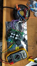
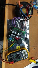
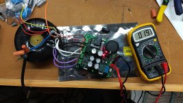
Finished up my MK2 Power Supply. Still waiting for my choke and Buck to arrive and the connector for the High Voltage doesn't look correct as it only has one pin. Need to go back to Mouser and find the right one.
Pics of High Voltage out, pre timer and post timer and the output for the DC/DC buck.
No pics for the driver/bias outputs, but they are 19v and -149v.
A few Notes:
The 10 ohm R14 and the 10K ohm R15 are tricky to get in there as there is little space for 5W resistors.
Make sure to purchase the correct connector for the HV.
Be careful of the polarity on the LEDs, it's not listed on the screen printing on the board.
gabo
Attachments
Nice work Gabo!
Those 5’watters are tucked in tight, I hope they don’t get to hot under load.
Yea I'm a little concerned about that as well. I actually bought several different ones trying to find something small.
I angled the 10K one up to give it a bit of room underneath to try to give that NTC a bit of room, but it's not much.
We'll see eventually.
gabo
gabo,
Thanks for sharing you progress and findings. Very helpful and we are enjoying the process as well as gaining insight.
By my calculation R14 (10 Ohm) dissipates around 0.4 watts steady state, so a 2 watt resistor should be fine. The 10k resistor will dissipate a lot more than 5 watts initially, but goes to zero when the switch bypasses it a few seconds later. I might install the PSU board vertically against a chassis side and put 10k between the board and against the chassis for some additional thermal mass and heat sinking.
Good luck with you build.
- Home
- Amplifiers
- Tubes / Valves
- EL34 Baby Huey Amplifier