Hello all,
I also received a comment/ suggestion from a gentleman that BHEL34 can also use 6V6 tubes. I am no expert on tubes , so if someone is willing , they could post a detailed write up on how to do it manually on the existing BHEL34 PCBs.
regards
prasi
PS as usual, PCBs will be 2.4mm thick, 70 um copper , ENIG-gold , green mask and white silk.
HI
Only change of components equal to BH84
A game PCBs, if there is no GB BH84, I will adapt it for my stock of 6P14P-EB and TFK ;-)
Best Regards
Fernan
Test Drive of my BH
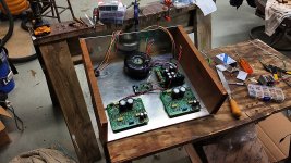
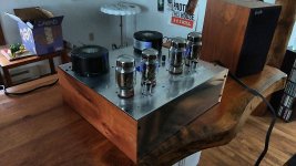
Today I put together my BH to take her for a test spin. It sounds great.
Now I am waiting on covers from ebay for my output transformers. When I get those, I will take it back apart, drill the holes for them and paint the chassis.
In the meantime, it's got that junkyard dog look, but sounds good!
Here are pictures of fitting the boards in the chassis and the fully assembled and playing BH.
gabo
Attachments
Today I put together my BH to take her for a test spin.
Now I am waiting on covers from ebay for my output transformers. When I get those, I will take it back apart, drill the holes for them and paint the chassis.
gabo
Gabo,
Congratulations! Well done! Quick question about your transformer covers - do you mind providing a link for them? I assume you are using the Toroidy KT88PP outputs.
Thanks,
Francois
KT88PP Covers
Yes, I purchased these off ebay. Unfortunately, ordering from the US, I could not find the variant of the KT88P that shipped with the factory covers. So I purchased them without covers.
I spent some time measuring various cans in the shop and the cupboard to see if I could find something I could make covers out of. Turns out a quart paint can is close and could probably be used with a little effort.
But then I found these on ebay, they seem to be the correct size, we'll see for sure when they arrive. I'll certainly come back here and update my final build. But with the coronavirus affecting shipments from China and the normal long shipping time, it may be another month or more before I receive them.
120*66mm +-0.5 Metal Shield Toroid Transformer Cover box Protect Chassis Case | eBay
gabo
Gabo,
Congratulations! Well done! Quick question about your transformer covers - do you mind providing a link for them? I assume you are using the Toroidy KT88PP outputs.
Thanks,
Francois
Yes, I purchased these off ebay. Unfortunately, ordering from the US, I could not find the variant of the KT88P that shipped with the factory covers. So I purchased them without covers.
I spent some time measuring various cans in the shop and the cupboard to see if I could find something I could make covers out of. Turns out a quart paint can is close and could probably be used with a little effort.
But then I found these on ebay, they seem to be the correct size, we'll see for sure when they arrive. I'll certainly come back here and update my final build. But with the coronavirus affecting shipments from China and the normal long shipping time, it may be another month or more before I receive them.
120*66mm +-0.5 Metal Shield Toroid Transformer Cover box Protect Chassis Case | eBay
gabo
Last edited:
Thanks Prasi, Have you heard anything about Marc? I sure hope he's doing ok.
gabo
Unfortunately no. I have written him twice but not received reply. I too hope that he is well and probably busy with work.
may be Philippe who is close by , can tell us.
Yes, I purchased these off ebay. Unfortunately, ordering from the US, I could not find the variant of the KT88P that shipped with the factory covers. So I purchased them without covers.
I spent some time measuring various cans in the shop and the cupboard to see if I could find something I could make covers out of. Turns out a quart paint can is close and could probably be used with a little effort.
But then I found these on ebay, they seem to be the correct size, we'll see for sure when they arrive. I'll certainly come back here and update my final build. But with the coronavirus affecting shipments from China and the normal long shipping time, it may be another month or more before I receive them.
120*66mm +-0.5 Metal Shield Toroid Transformer Cover box Protect Chassis Case | eBay
gabo
Hello Gabo what bias do you need with the KT88?
cordially
KT88 Bias
For my KT88s, I'm using 40ma bias, which I was lazy and found at this web site.
Tube Bias Calc
Instead of downloading the data sheet and doing the calcs manually. That's probably very low and conservative, I think a 70% calc would put me somewhere in the 53-55ma range.
I have the meter that was recommended on the top of my amp, with a switch and the pot adjustments exposed. So I can easily change my bias point at any time.
gabo
Last edited:
KT88 Bias
Actually, now that I look at the data a bit closer. I think I'll change my bias to about 55ma for my KT88s.
That puts me squarely in the 70% range, which is probably about right.
gabo
Actually, now that I look at the data a bit closer. I think I'll change my bias to about 55ma for my KT88s.
That puts me squarely in the 70% range, which is probably about right.
gabo
Anyone try KT120s or even KT150s in their EL34 BH MK2? I think the only issue is the increased heater current, which with the buck converter shouldn't be a problem.
To bias it correctly it will also require a bit more bias current, but I don't think that's a problem either.
Curious if anyone has tried them.
gabo
To bias it correctly it will also require a bit more bias current, but I don't think that's a problem either.
Curious if anyone has tried them.
gabo
Hello,
what is the value of r39 because on the diagram it is 15k and in the bom it is 18k.
I ordered the power transformer at toroidy as recommended by Marc, is there an advantage to supply with the voltage of the winding 330v instead of 275v (I mounted capacitors 500v)?
what is the value of r39 because on the diagram it is 15k and in the bom it is 18k.
I ordered the power transformer at toroidy as recommended by Marc, is there an advantage to supply with the voltage of the winding 330v instead of 275v (I mounted capacitors 500v)?
....<snip> ..value of r39 because on the diagram it is 15k and in the bom it is 18k.
..<snip> ., is there an advantage to supply with the voltage of the winding 330v instead of 275v (I mounted capacitors 500v)?
I totally agree with gabo. I searched for an inconsistency in r39 in published schema vs. BOM values but could not find it. Please let us know if there is an error somewhere unnoticed.
Also agree with using the 330 VAC winding if you build for EL34 or KT88 output tubes. 275Vac would be better for 6V6 or 6L6GB tubes. You can check what Marc said about it in post #594, predicting theoretically 460Vdc with the 330 Vac winding; in practice gabo measured 437 Vdc in the handy voltage chart he posted in #655.
Gabo, correct me if I’m wrong, but I believe you measured it unloaded, i.e. without output tubes installed. It would be helpful if you could measure and publish the voltages when fully loaded, at you new operating point, I think you said 50-55 ma per KT88. I‘m looking forward to your assessment of performance at the “hotter” point.
Last edited:
Hey Francois, yes that is my voltage using the MK2 power supply board with the toroidy 250/001 transformer and the 330Vac. And that was unloaded, meaning the output tubes were removed but the 12ax7 was installed.
That's a good idea on making a new chart with fully loaded voltages, I'll try to do that sometime this next week.
As for the 50-55ma bias point, I did not really hear much of a difference. So I backed off a bit and have settled (for now) on a bias point of 48ma. I've run them as low as 40ma but the amp seems better just a bit higher.
The amp sounds fantastic after quite a bit of listening. However, it does get really hot, so I have taken it out of service and have it back in the shop. I'm going to cut some more venting holes in my chassis and I have also ordered a fan. I'm going to mount a standard PC chassis fan on the bottom cover. It's sort of an odd place to put a fan, but I don't have room on the back and don't want it on the front.
With the feet I have on my chassis, it'll be ok on the bottom. I have ordered a 115Vac fan so I can connect it directly to the mains input and not load up my PSU with that. I'm also going to put a resistor in serial with it to turn it down to a fairly slow speed to keep it quiet. I guess I could mount a pot on the back to turn it up/down, but I think just a fixed resistor is ok. I'll have to size it when I get the fans.
The idea is to just provide a bit of airflow from the bottom up through some holes in the top, keeping the noise (and dust) to a minimum. I did also order the filter for the fan to help keep the dust out.
gabo
Hey gabo, thanks or the great update!
I especially appreciate hearing about your experience with heat build-up in the chassis - you sure saved me some headaches there. I would think a small bit of airflow to pump out the heat out of the tube holes in the top plate, plus any additional hole you are planning will be sufficient. Any idea if there is any unusual source of the heat? Good luck with the cooling measures you are taking.
Looking at the thread on diyAudio for KT150 operating points seemed to indicate you should be able to do it in a BH PCB, but the tube will be under-utilzed, unless you increase the high-voltage supply. I was concerned about the -bias supply, but the KT150 does not appear to need special treatment in this regard. (As you may recall the original GB BHEL34 board had trouble providing enough -bias for KT88s, which was one of the main reasons for going to the mk2 circuit.)
The datasheet for KT150 is here: https://www.tungsol.com/specs/kt150-tung-sol.pdf
Doesn't seem to be any unusual source of the heat, it just builds up after running it for a while. If I run it for two hours, then quickly remove the bottom plate and use an infrared thermometer, I find spots that are as high as 125 degrees F around the power supply. Which isn't just incredibly high, but that's in my shop which at this time of year is around 60 degrees F, so if you were in some place warm in the summer it might get pretty hot in there.
Just to keep it running for many years without problems, I think a bit of air flow is going to help out a lot.
Thanks for the info on the KT150, I agree with your assessment. The power I'm getting out of the KT88s seems to be good for my use, so I'll probably stick with those.
gabo
Just to keep it running for many years without problems, I think a bit of air flow is going to help out a lot.
Thanks for the info on the KT150, I agree with your assessment. The power I'm getting out of the KT88s seems to be good for my use, so I'll probably stick with those.
gabo
Hello François,
I have the Pcb first versions rev 2.1 and I used the diagram and the bom of the first post of Marc. What is the difference between the first version and the MK2 apart from the fact that the power supply is separate? You say that the bias is limited in the first version for the kt88 why? It is the same pattern normally. Sorry to ask so many questions i'm really new to tubes
Steven
Hi,
may I know if the PCBs of the current GB are including PSU, or it has to be bought separate?
Thanks
may I know if the PCBs of the current GB are including PSU, or it has to be bought separate?
Thanks
BH EL34 MK2 if it has a separate source, BH EL84 understand that it is the latest version and does not need,
in both you can make the modification of the PSU PCB....... , requested separately, for MK2 if recommended
in both you can make the modification of the PSU PCB....... , requested separately, for MK2 if recommended
Last edited:
- Home
- Amplifiers
- Tubes / Valves
- EL34 Baby Huey Amplifier