Hello Marc,
That's very nice indeed.
I have 2 general suggestions to make.
1. Those nets which carry high voltage, you can define them to have min clearance as per regulation , approx min 2.54 mm for 230VAC.
2. Pads can be made bigger for repeated soldering desoldering via the restring option in eagle under DRC setting .
Regards
Prasi
Thank you for the complements on my build Marc. One thing that would be nice IMO would be the ability to wire the tubes for 12v operation as well as 6. In my build I cut a couple of traces and added jumpers in order to run the EL34 filaments in series and wire up the 12ax7 for 12v as well.
The advantage is that it is easier to find good quality linear or switching power supplies for 12v then for 6v. The current is 1/2 of the 6v value, so for el34 it would be about 1.7 amps at 12v.
For EL84 versions total current would only be about 1amp.
About the current source running to +bias voltage - I was trying to maximize the drive voltage when using KT88. I fond that when I breadboarded the current source with the 220k resistor connected to the driver mosfet, (the stock connection), there was a substantial variation in the CCS current as you begin to drive large negative voltages. There is not enough base current available to eep the ccs transistor turned on with large negative voltage swings. This caused distortion on the waveform at high output levels. When I ran the 220k from my +bias supply of 22v the CCS current was much more consistent throughout the entire dynamic range off the driver and the waveform distortion was not present unless you clipped the driver by actually running out of - voltage swing.
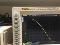
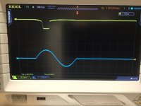
I got cut off by the 30 minute edit rule! I want to explain the 2 photos. The one on the left is the distortion in the speaker output waveform that occurs when you run out of - bias swing. The notch you see near the top of the close up of a sine wave. The one on the right (top waveform)is the voltage across the 390ohm current source resistor. The bottom one is input sine wave. You can see that the current source resistor voltage, which is analogous to current, changes slowly through the sine wave on either side of the positive peak. As the voltage output peaks the current is completely cut off. The other tube of the PP pair has the same waveforms on the opposite polarity of the sine wave.
I’m not sure what this sounds like but it is certainly not what we want to see in the output. Keep in mind that I was pushing the driver for max output due to my choice of tube HV and output transformer. After experimenting with KT88 at 450v 60ma, 425v 65ma and 400v 70ma I think I liked the lowerHV, higher bias current combo the best. Slightly less power output but that never seemed to be a concern for my speakers, room size and listening preferences. It sounded seriously good!
The advantage is that it is easier to find good quality linear or switching power supplies for 12v then for 6v. The current is 1/2 of the 6v value, so for el34 it would be about 1.7 amps at 12v.
For EL84 versions total current would only be about 1amp.
About the current source running to +bias voltage - I was trying to maximize the drive voltage when using KT88. I fond that when I breadboarded the current source with the 220k resistor connected to the driver mosfet, (the stock connection), there was a substantial variation in the CCS current as you begin to drive large negative voltages. There is not enough base current available to eep the ccs transistor turned on with large negative voltage swings. This caused distortion on the waveform at high output levels. When I ran the 220k from my +bias supply of 22v the CCS current was much more consistent throughout the entire dynamic range off the driver and the waveform distortion was not present unless you clipped the driver by actually running out of - voltage swing.
I got cut off by the 30 minute edit rule! I want to explain the 2 photos. The one on the left is the distortion in the speaker output waveform that occurs when you run out of - bias swing. The notch you see near the top of the close up of a sine wave. The one on the right (top waveform)is the voltage across the 390ohm current source resistor. The bottom one is input sine wave. You can see that the current source resistor voltage, which is analogous to current, changes slowly through the sine wave on either side of the positive peak. As the voltage output peaks the current is completely cut off. The other tube of the PP pair has the same waveforms on the opposite polarity of the sine wave.
I’m not sure what this sounds like but it is certainly not what we want to see in the output. Keep in mind that I was pushing the driver for max output due to my choice of tube HV and output transformer. After experimenting with KT88 at 450v 60ma, 425v 65ma and 400v 70ma I think I liked the lowerHV, higher bias current combo the best. Slightly less power output but that never seemed to be a concern for my speakers, room size and listening preferences. It sounded seriously good!
Attachments
I’m not sure what this sounds like but it is certainly not what we want to see in the output. Keep in mind that I was pushing the driver for max output due to my choice of tube HV and output transformer. After experimenting with KT88 at 450v 60ma, 425v 65ma and 400v 70ma I think I liked the lowerHV, higher bias current combo the best. Slightly less power output but that never seemed to be a concern for my speakers, room size and listening preferences. It sounded seriously good!
Brian, I know it would be speculation, but please indulge. What do you expect if you had a Toroidy 4k output transformer rather than the 6.6k you currently use as load impedance?
Last edited:
I would expect it to sound very similar. Same wide bandwidth, low distortion transformer performance. You would be able to get more power out for a given HV. You will have a bit more gain using the 4K. Your output impedance will be a bit higher open loop. You can reduce it by using feedback if you want to go that route. The sound you get will also depend on your power supply. If you are running high efficiency speakers I would recommend a clc filtered supply for lower noise. It’s pretty easy to experiment with the power supply as long as you have room to fit a choke into the chassis.
I intended to get the 4K transformer but ended up getting the 6600 by mistake. So I needed to squeeze as much output from the driver circuit as possible.I also got a pair of 8k for BHel84 on the same order.
I’m thinking the EL84 BH will be a really nice amp as well. I just don’t have time to build it right now. I still haven’t listened to the set of Tung Sol el34s I bought for BH.
Hello Prasi,
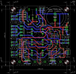
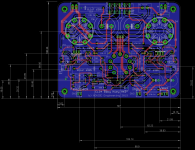
I have followed your recommendation and slightly increase the restring from 25% to 30% but I cannot do more because it will reduce the clearance between track and pad 🙁
As you can see the board is quite full now since I want to keep it in the 10 cm per side limit ! I will send the Gerber files to the PCB manufacturer soon therefor tell me if you find some errors 😕
I am still working on the amplifier layout to be sure that I will have the same components location to have the possibility to retrofit existing amplifier...
Best regards,
Marc
Attachments
Hello Marc,
This is looking very good.
Amazing thing is you managed everything to fit on 10cm x 10cm. Congratulations🙂.
regards
Prasi
This is looking very good.
Amazing thing is you managed everything to fit on 10cm x 10cm. Congratulations🙂.
regards
Prasi
Hi Prasi,
Yes it was quite hard to fit everything in this size, but it was a good exercice and now the PCB are in production by JLCPCB 🙂 I changed from PCBWay after my last delivery problem with E-Packet and since I learned that JLCPCB was the same price than PCBWay of 5$ for 10 boards BUT they charge only 17$ for shipment by DHL instead of 25 !!!
I have also worked on the Baby Huey MK2 and I found that the layout was not completely symmetric and I had to move the tubes by 1.27 mm and therefor to move a lot of other components 🙁 Now I am close to finish it and you can see a comparison of the two version, remember that the first version was a top view while the new version is a bottom view with the serigraph for all components on the bottom.
Will you make a GB for the MK2 if there is enough interest 😀
Rgds,
Marc
Attachments
I am ready for those gerber files! I haven't buillt an amp in a decade but your layout really appeals to me! awesome work.
Hi Marc,
If the GB happens, please put me down for a pair of the EL34 v2.0 and a pair of the PS boards.
Thanks.
If the GB happens, please put me down for a pair of the EL34 v2.0 and a pair of the PS boards.
Thanks.
well done....The caps are on the bottom and the tubes on the top
Hello Marc,
Yes, JLCPCB (and also elecrow ) produce neat little PCBs with cheaper shipping options. BTW, nice layout.
Yes I can make the GB for MK2 if there is enough interest.😎
regards
Prasi
Yes, JLCPCB (and also elecrow ) produce neat little PCBs with cheaper shipping options. BTW, nice layout.
Yes I can make the GB for MK2 if there is enough interest.😎
regards
Prasi
Yes I can make the GB for MK2 if there is enough interest.😎
Hi Prasi and Marc,
I’d be interested in the BHEL34 MK2 and psu board 🙂
Best,
Vunce
I would also be interested in BHEL34 Mk2 even though I have not started on making the BHEL34. Hopefully, I'll get my BHEL34 boards tomorrow.
I wanted others opinion on a monoblock build. Here's a prelim drawing. I'm concerned about the space between the mains and OPTs.
Am I being choosy or is that fine ?
The design is a top plate with wooden body around.
Could somebody please help answer if this spacing is fine ?
Attachments
Yes your design look OK, but I recommend to turn the Baby Huey board in the reverse direction to have the input triode not close to the transformer because the input stage is more sensitive to transformer magnetic field than the output tubes 🙂
In the mean time I have made some more change on the MK2 PCB and I hope there is no error ? It is ready to be produced by Prasi if there is enough interest ? I made the modification suggested by bfpca and connected the MOSFET CCS directly to the +15 V and I increased the bias voltage to -100 V. I have also added a jumper to select ECC83 or 6N2P pinout for the input tube like in the last EL84 Baby Huey... I remind you that this version has not been tested but the schematic is the same except the two point explained before ! Anyway, I will appreciate if some of the expert reading this forum give me their feedback before we produce the PCB 😀
In principle I will receive the Power supply PCB soon and I will test it with the existing Baby Huey PCB (after removing the rectifiers of course) and let you know if it work well...
Rgds,
Marc
Attachments
- Home
- Amplifiers
- Tubes / Valves
- EL34 Baby Huey Amplifier