You can increase the damping factor by connecting the cathode resistor with one end the secondary of the output transformer and grounding the other end. If connected correctly you get negative feedback resulting in both lower distortion and higher damping (and somewhat lesser sensitivity of course) connected wrongly sensitivity increases and/or oscillation will occur. In that case simply reverse the connections.

People in the RF business sometimes call that a comb generator.The spectrum analyzer is ready.
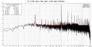
UL connexion of 43% usually gets a Damping Factor (DF) of about one.My friend suggests ultra linear connection for EL152.
Much better than a fraction of that.
Easy to try, the bias will need to be adjusted. 🙂
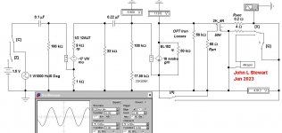
Using the circuit switches to set for no NFB or cathode NFB from the OPT secondary the Sim finds 5 db NFBYou can increase the damping factor by connecting the cathode resistor with one end the secondary of the output transformer and grounding the other end
And the Damping Factor is about One. Much better than no NFB. 👍
Attachments
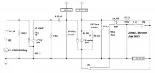
Impulse Testing
In these tests switches are operated by keys on the PC KB. Switch C selects Impulse or Sine Wave.
Switch X selects 4R or a speaker simulator load. Switch A selects VC to cathode FB. And switch Q open circuits the output.
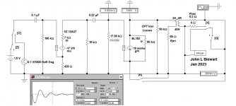
With the speaker sim connected & driven by an impulse by switch Z at the amp front end we see a large resonance
on the speaker simulator. With the VC to cathode NFB the resonance is completely damped out. 👍
In these tests switches are operated by keys on the PC KB. Switch C selects Impulse or Sine Wave.
Switch X selects 4R or a speaker simulator load. Switch A selects VC to cathode FB. And switch Q open circuits the output.
With the speaker sim connected & driven by an impulse by switch Z at the amp front end we see a large resonance
on the speaker simulator. With the VC to cathode NFB the resonance is completely damped out. 👍
Attachments
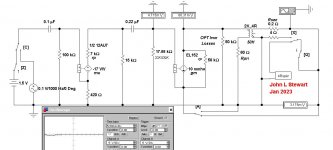

Improving the EL152 12AU7 SE amp
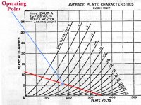
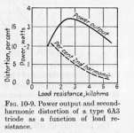
The front end 12AU7 circuit needs some adjustment. For any common triode, D% increases as the load decreases. Refer to the distortion curve vs load resistance for the 6A3 triode. The curve is generic & applies to any common triode. In theory max output occurs when Rl is 2 rp. In practice the relation is more like when Rl is 2.5 rp. But distortion is high, better to select a load somewhat higher.
For this load the tube rp should be at the current it is operating at, not the figure we see on the front page of the data sheet. So for the 12AU7 the rp of 7.7K is while the tube is conducting 10.5 mA. In the modified circuit the tube will be conducting 6 mA, so rp becomes 9K. Curves covering that are at the top of p3 on the GE 12AU7 data.
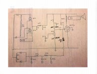
On the modified circuit drawing a 33K plate load is now used. And 100K has been added to the following grid resister. The real AC plate load includes the following tubes grid resister in parallel. The actual load on the 12AU7 plate becomes ~25.8K. In the original cct the total of Rl was 8.16K. Far too low.
The simulation indicates a one volt input generates a 6W output. And the DF of the final stage remains the same unchanged, the 12AU7 is not inside the cathode NFB. 👍
The front end 12AU7 circuit needs some adjustment. For any common triode, D% increases as the load decreases. Refer to the distortion curve vs load resistance for the 6A3 triode. The curve is generic & applies to any common triode. In theory max output occurs when Rl is 2 rp. In practice the relation is more like when Rl is 2.5 rp. But distortion is high, better to select a load somewhat higher.
For this load the tube rp should be at the current it is operating at, not the figure we see on the front page of the data sheet. So for the 12AU7 the rp of 7.7K is while the tube is conducting 10.5 mA. In the modified circuit the tube will be conducting 6 mA, so rp becomes 9K. Curves covering that are at the top of p3 on the GE 12AU7 data.
On the modified circuit drawing a 33K plate load is now used. And 100K has been added to the following grid resister. The real AC plate load includes the following tubes grid resister in parallel. The actual load on the 12AU7 plate becomes ~25.8K. In the original cct the total of Rl was 8.16K. Far too low.
The simulation indicates a one volt input generates a 6W output. And the DF of the final stage remains the same unchanged, the 12AU7 is not inside the cathode NFB. 👍
Attachments
Now THD is good although power is not full rated.Impulse Testing
In these tests switches are operated by keys on the PC KB. Switch C selects Impulse or Sine Wave.
Switch X selects 4R or a speaker simulator load. Switch A selects VC to cathode FB. And switch Q open circuits the output.
With the speaker sim connected & driven by an impulse by switch Z at the amp front end we see a large resonance
on the speaker simulator. With the VC to cathode NFB the resonance is completely damped out. 👍