
It's true, but with these parameters (300V, UL) the THD (and the power) comparable to 300B SE.Remember the screen grid voltage rating of 300 V. So you're very limited with a UL design.

Most Pentodes and Beam Power tubes have maximum screen voltage limits that "get in the way".
(EL152 below)
807:
Here is an example of history and theory:
807 screen was 300V maximum on early data sheets. (the tube was intended for Beam Power Mode). The screen voltage is constant at 300V.
When g1 voltage comes near the cathode voltage, the screen voltage is still at 300V, and so it draws Lots of screen current (danger zone if the screen's constant voltage is greater than 300V).
Then some designers started using the 807 in Triode Wired Mode (the later data sheets started listing 400V maximum for the screen, when in
Triode Wired Mode).
When g1 voltage comes near to the cathode voltage, the plate voltage is reduced, so the screen voltage is reduced equally too, and that keeps the screen current in the safe range.
Depending on the % of the UL tap, I estimate the maximum screen voltage of the 807 to be between 330V to 360V, (for reasonably safe/long life)
when in Ultra Linear Mode.
When g1 grid voltage comes near to the cathode voltage, normally the screen would draw Lots of current; However, as g1 grid voltage goes up, the plate voltage goes down, and so the screen voltage goes down too (at the UL tap % rate). With the screen voltage reduced, it draws far less current.
So the maximum screen voltage can be somewhat higher than the beam power mode rating.
EL152:
Perhaps the EL152 has a maximum screen voltage rating for Triode Wired Mode.
If so, then the maximum screen voltage rating should fall somewhere between the pentode and triode wired modes.
Tubes are funny that way, they can successfully be used differently than the intent of the original designers.
Last edited:
popa marius,
ThanksI
I did not even get finished with my edits of added information, and you already gave me a like.
ThanksI
I did not even get finished with my edits of added information, and you already gave me a like.
Not to derail the thread but I’m curious about triode 807 settings. You say the data sheets were changed for triode mode, does that reflect a difference in the tubes that were being made or simply a re-evaluation of what existing tubes could do? I’m currently running 807 (actually vt60a) at 320v 40mna with 8k transformers in triode mode. Love it. Would enjoy pumping up the voltage some to get just a bit more power. 400v sounds tasty…Most Pentodes and Beam Power tubes have maximum screen voltage limits that "get in the way".
(EL152 below)
807:
Here is an example of history and theory:
807 screen was 300V maximum on early data sheets. (the tube was intended for Beam Power Mode). The screen voltage is constant at 300V.
When g1 voltage comes near the cathode voltage, the screen voltage is still at 300V, and so it draws Lots of screen current (danger zone if the screen's constant voltage is greater than 300V).
Then some designers started using the 807 in Triode Wired Mode (the later data sheets started listing 400V maximum for the screen, when in
Triode Wired Mode).
When g1 voltage comes near to the cathode voltage, the plate voltage is reduced, so the screen voltage is reduced equally too, and that keeps the screen current in the safe range.
Depending on the % of the UL tap, I estimate the maximum screen voltage of the 807 to be between 330V to 360V, (for reasonably safe/long life)
when in Ultra Linear Mode.
When g1 grid voltage comes near to the cathode voltage, normally the screen would draw Lots of current; However, as g1 grid voltage goes up, the plate voltage goes down, and so the screen voltage goes down too (at the UL tap % rate). With the screen voltage reduced, it draws far less current.
So the maximum screen voltage can be somewhat higher than the beam power mode rating.
EL152:
Perhaps the EL152 has a maximum screen voltage rating for Triode Wired Mode.
If so, then the maximum screen voltage rating should fall somewhere between the pentode and triode wired modes.
Tubes are funny that way, they can successfully be used differently than the intent of the original designers.
With a 40% UL tap I’m guessing keeping the voltage at 320 would be fine If I flip the switch to UL?
I would suggest adding a small screen resister to measure the current through screen.
The screen is bound by Pg2 (screen power) , we will blow up screen if we exceed the maximum rating of Pg2.
KT66 KT88 have lower screen current . Is it due to looser screen winding?
The screen is bound by Pg2 (screen power) , we will blow up screen if we exceed the maximum rating of Pg2.
KT66 KT88 have lower screen current . Is it due to looser screen winding?
HIFIDIY论坛-中秋假期贴:无产品级别的单端设计,纯真之源终于更新,1楼完成列表,346楼重要更新 - Powered by Discuz! http://bbs.hifidiy.net/forum.php?mod=viewthread&tid=1488407&extra=page=1这个月我完成了 EL152 五极管单功放。德律风根功放与300B功放相比,声音光彩、平衡。不强调低音。目前EL152由ECC88驱动。以后ECC88会被ECC82取代。View attachment 1124216
You can refer to it
HIFIDIY论坛-中秋假期贴:无产品级别的单端设计,纯真之源终于更新,1楼完成列表,346楼重要更新 - Powered by Discuz! http://bbs.hifidiy.net/forum.php?mod=viewthread&tid=1488407&extra=page=1
You can refer to it

Please ensure all content is in English.
HIFIDIY Forum - Mid-Autumn Festival Holiday Sticker: Single-ended design without product level, the source of innocence is finally updated, the 1st floor completion list, the 346th floor important update - Powered by Discuz! http://bbs.hifidiy.net/forum.php?mod=viewthread&tid=1488407&extra=page=1This month I finished the EL152 Pentode Single Power Amplifier. Compared with the 300B amplifier, the sound of the Telefunken amplifier is brilliant and balanced. Bass is not emphasized. Currently EL152 is driven by ECC88. ECC88 will be replaced by ECC82 in the future. View attachment 1124216
isaacc7,
If I understand correctly, there were no essential changes to the 807 design, materials, and production of the original 807.
But then the new data specifications added a specification: triode wired maximum screen voltage of 400V.
Your 807 amplifier might run OK at 400V.
But be sure that the maximum plate watts, maximum screen watts are not exceeded when you go to 400V.
Perhaps you will have to change the g1 grid bias, in order to reduce the cathode current (cathode current is the total of the plate and screen current).
The reason is to keep within those maximum plate and screen watt disipation specifications.
400V @ 40mA, should be OK.
There will be more than 40mA at 400V if you do not change the bias voltage.
The question is, what is the current when you increase the plate voltage to 400V, but do not change the g1 bias voltage. Will the new plate voltage and plate current exceed the maximum plate + screen dissipation rating?
If you have to change the g1 grid bias and therefore maintain or reduce the cathode current, the plate resistance, rp, might increase.
And that might require a higher output transformer primary impedance; in order to get the additional output power, and to keep the distortion the same amount as your lower powered 807 that are at 320V.
And, is your output transformer rated for just 40mA, or for more current than that?
A very old recommendation about more amplifier power: A modified amplifier, or a new power amplifier that does not double the output power is not worth changing (typically, if everything else remains the same, you need at least 3dB more power to really notice much change when you listen).
Last edited:
el152,
You said: "KT66 KT88 have lower screen current . Is it due to looser screen winding?"
1. Did you mean lower screen current at exactly the same quiescent operating conditions:
(At the same g1 bias, plate voltage, and screen voltage).
Example: -14 V g1 bias, 300V plate, and 300V screen.
If the data sheet g1 bias, plate volts, and screen volts are not the same from one tube type to the other tube type, then of course the screen current can be different.
2. If the g1 bias, plate volts, and screen volts are the same for the 807, KT66, and KT88, what else could make for a different screen current?
Screen to cathode spacing
Screen to plate spacing
The screen wire turns pitch (that you mentioned)
Or perhaps something else
3. 807 and KT66 maximum screen dissipation is 3.5 Watts.
KT88 maximum screen dissipation is 8 Watts.
Just one of many other differences.
4. Run any one of those tubes in Triode wired mode:
Plate/screen voltage x plate/screen current = plate/screen dissipation.
A. At High plate/screen voltage, and low current to maintain the maximum plate/screen dissipation.
B. At Low plate/screen voltage, and high current to maintain the maximum plate/screen dissipation.
Then, the plate resistance, rp, will be lowest in condition B; and rp will be higher in condition A.
Last edited:
The only technique to decrease screen current that I'm aware of is to have both the control and screen grids wound in the same pitch and get them aligned so that the screen is in the control grid shadow.
Best regards!
Best regards!
Yes your comment is right.el152,
You said: "KT66 KT88 have lower screen current . Is it due to looser screen winding?"
1. Did you mean lower screen current at exactly the same quiescent operating conditions:
(At the same g1 bias, plate voltage, and screen voltage).
Example: -14 V g1 bias, 300V plate, and 300V screen.
If the data sheet g1 bias, plate volts, and screen volts are not the same from one tube type to the other tube type, then of course the screen current can be different.
2. If the g1 bias, plate volts, and screen volts are the same for the 807, KT66, and KT88, what else could make for a different screen current?
Screen to cathode spacing
Screen to plate spacing
The screen wire turns pitch (that you mentioned)
Or perhaps something else
3. 807 and KT66 maximum screen dissipation is 3.5 Watts.
KT88 maximum screen dissipation is 8 Watts.
Just one of many other differences.
4. Run any one of those tubes in Triode wired mode:
Plate/screen voltage x plate/screen current = plate/screen dissipation.
A. At High plate/screen voltage, and low current to maintain the maximum plate/screen dissipation.
B. At Low plate/screen voltage, and high current to maintain the maximum plate/screen dissipation.
Then, the plate resistance, rp, will be lowest in condition B; and rp will be higher in condition A.
From EL152 datasheet, screen current is 20mA @ 250V in pentode connection. It may imply 5W max power dissipation of screen. Indeed there are variables to affect the screen current.
Best Regards
1. If the screen wire was very thick, it could shield some electrons from "seeing" the plate, so more electrons go to the screen - more screen current.
Then a thinner screen wire would make more electrons "see" the plate, and go to the plate.
But thinner screen wires might not have as much maximum dissipation capability.
And, they might deform easier than a thick screen wire.
2. The EL152 screen current @ 250V, depends on g1 grid voltage versus the cathode voltage (and is also influenced by the plate voltage too).
At a fixed g1 voltage, if the plate voltage is very low, the screen current may increase greatly. There are screen current curves that show this.
Less than 20mA screen current is possible at higher negative g1 voltages, but the plate current will be reduced too.
3. I forgot all about making the g1 and g2 grid pitches equal, and doing critical alignments.
4. The g1 grid wires and g2 wires might use the same wire diameter.
But g1 is very close to a heat source, the cathode. KT88 filament is 1.6A at 6.3V (10.08 Watts).
g2 is a little further away to a heat source, the plate. KT88 plate max dissipation is 42 Watts.
Note: KT88 max plate diss is 42 Watts, max screen diss is 8 Watts, But the maximum combined plate + screen dissipation is only 46 Watts
(not 50 Watts).
The total of all the heat sources in the glass envelope matters.
Last edited:
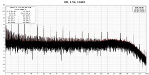
Thank you for your simulation. The spectrum analyzer is ready.It's true, but with these parameters (300V, UL) the THD (and the power) comparable to 300B SE.
View attachment 1125566
Attachments
Yes damping factor is an issue. By now there is only local feedback by cathode resistor. UL or global feedback is undergoing. Max 14W output @ 300V supply is really challenging.Looks nice but there is minimal loudspeaker damping as connected.
300B amps always have damping due to triode connected Rl / rp. 🙂
- Home
- Amplifiers
- Tubes / Valves
- EL152 Single End Amplifier