Some sketching…maybe to simplified…
Based on:

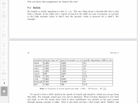
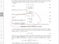
Assuming:
Carbon fibre density 1.5 x10^3 kg/m^3
Carbon fibre speed of sound 340 m/s, I’m using the bending wave speed att the coincidence frequency, not the longitudinal speed.
This gives an impedance of 1.5x 340=510 Pas/m
From the first table EPDM impedance = 243 Pas/m
From the last picture reflection coefficient = (Z1-Z2)/(z1+Z2) => (510-243)/(510+243)=0.35 i.e. 35% of the wave i reflected back in to membrane.
Questions:
Is it correct to use the bending wave speed? It varies with frequency thus the impedance will vary. B&w use an avarage cone impedance.
Is epdm able to convert the wave energy in to heat?
The density of epdm is critical. I have used a number of different epdm material from rather soft foam to more rubber like with different densities.
I should re-check them.
Thomas
Based on:


Assuming:
Carbon fibre density 1.5 x10^3 kg/m^3
Carbon fibre speed of sound 340 m/s, I’m using the bending wave speed att the coincidence frequency, not the longitudinal speed.
This gives an impedance of 1.5x 340=510 Pas/m
From the first table EPDM impedance = 243 Pas/m
From the last picture reflection coefficient = (Z1-Z2)/(z1+Z2) => (510-243)/(510+243)=0.35 i.e. 35% of the wave i reflected back in to membrane.
Questions:
Is it correct to use the bending wave speed? It varies with frequency thus the impedance will vary. B&w use an avarage cone impedance.
Is epdm able to convert the wave energy in to heat?
The density of epdm is critical. I have used a number of different epdm material from rather soft foam to more rubber like with different densities.
I should re-check them.
Thomas
@Sandasnickaren
Hello Thomas,
You have lost me in the impedance. I had in mind previously the mechanical impedance which links speed and force in the material. Here it is acoustical impedance between pressure and flow (wave speed?);
Hello Thomas,
You have lost me in the impedance. I had in mind previously the mechanical impedance which links speed and force in the material. Here it is acoustical impedance between pressure and flow (wave speed?);
Panel mechanical impedance and natural frequency are related, as the panel's mechanical impedance determines the panel's natural frequency.
But they are not the same. The point of minimum impedance corresponds to the natural frequency of the plate.
Veleric uses impact method, maybe he can use it to measure the mechanical impedance of a panel.
It is correct to use the bending wave speed in the calculation of the acoustic impedance. The bending wave speed is a measure of the speed at which a bending wave travels through the material, and it can be used to determine the material's acoustic impedance.
Bending wave speed can vary with frequency, and therefore the impedance calculated will also vary with frequency. This is known as frequency dependent impedance.
One can calculate the mechanical impedance by knowing the acoustic impedance (or the other way around) of a material.
It is important to note that the correlation between the two types of impedance is not always straightforward, as the relation between mechanical properties and the density of the material can be complex and non-linear, especially in composite materials.
B&W use mechanical not acoustic impedance as close as possible to the mean value of the cone.
Christian,This is also the typical aspect of a DML to show mainly a resistive impedance to the exciter (8.sqrt(B.µ))
So the next question for me is : how to find and charaterized such material?
Having a look to the white papers in the previous link about sorbothane, I was not sure it is apurely resistive material.
Any idea?
Christian
I noticed the same wording myself yesterday. By "resistive" do they mean viscous (i.e. damping)? That is, that its deformation dissipates energy by creating heat rather than storing it as potential or kinetic energy?
Eric
Guys,
For what it's worth, here's the NXT patent that covers damping. As always, it's a lot to read. I'll try...again...
Eric
https://patentimages.storage.googleapis.com/ea/0e/93/9583fcf9a1db27/US20020044668A1.pdf
For what it's worth, here's the NXT patent that covers damping. As always, it's a lot to read. I'll try...again...
Eric
https://patentimages.storage.googleapis.com/ea/0e/93/9583fcf9a1db27/US20020044668A1.pdf
Thank you Lenta for the help on the topic. You remind me to share that there is one element almost never used here which is the electrical impedance of a DML. I did only once a measurement of the electrical impedance of a panel. It is what is in some papers. Unfortunately I can't search for now sources but the general shape is like a constant value (resistance) followed by a rising portion due to the inductance of the voice coil and in low to mid frequencies some "peaks" which are the reflect of mechanical resonances seen by the exciter (I am wondering if I have already posted around that). I think we should push on how to use it to get practical information about the modes, the damping of the panel, the effect of the surrounding (related to the height of the peaks?)Panel mechanical impedance and natural frequency are related, as the panel's mechanical impedance determines the panel's natural frequency.
But they are not the same. The point of minimum impedance corresponds to the natural frequency of the plate.
Veleric uses impact method, maybe he can use it to measure the mechanical impedance of a panel.
It is correct to use the bending wave speed in the calculation of the acoustic impedance. The bending wave speed is a measure of the speed at which a bending wave travels through the material, and it can be used to determine the material's acoustic impedance.
Bending wave speed can vary with frequency, and therefore the impedance calculated will also vary with frequency. This is known as frequency dependent impedance.
One can calculate the mechanical impedance by knowing the acoustic impedance (or the other way around) of a material.
It is important to note that the correlation between the two types of impedance is not always straightforward, as the relation between mechanical properties and the density of the material can be complex and non-linear, especially in composite materials.
B&W use mechanical not acoustic impedance as close as possible to the mean value of the cone.
Christian
That's my understanding. Not a mass effect, not a spring effect but a damper effect that tranform the energy to heat (like sorbothane?). Having some reading around sorbothane, it is to be far from simple or at least, a fully new area for me.Christian,
I noticed the same wording myself yesterday. By "resistive" do they mean viscous (i.e. damping)? That is, that its deformation dissipates energy by creating heat rather than storing it as potential or kinetic energy?
Eric
Christian
Some bugs yes in the "quote" button!
If somebody can help on it it will be great for this topic.
Excellent. The patent I have never really understood... I think in this one it is explained that the modes are not the key point for a panel to make sound but it is its finite geometric aperture.Guys,
For what it's worth, here's the NXT patent that covers damping. As always, it's a lot to read. I'll try...again...
Eric
https://patentimages.storage.googleapis.com/ea/0e/93/9583fcf9a1db27/US20020044668A1.pdf
If somebody can help on it it will be great for this topic.
Christian,
I've been reading that patent (not finished yet) and came across this formula for the mechanical impedance of the "end of the beam" which I did not recall. Note, in this case it is a beam not a panel, but that should not matter much.
His expression is not the same as the infinite panel impedance we are familiar with.
Also, it's curious that he defines this parameter k as the "wavevector", when I think it is simply the bending wave speed.
Eric
Odd, it seems the quote button is available lately only for the second to last post, but not the latest post.Some bugs yes in the "quote" button!
Excellent. The patent I have never really understood... I think in this one it is explained that the modes are not the key point for a panel to make sound but it is its finite geometric aperture.
If somebody can help on it it will be great for this topic.
I have always been a bit skeptical about this finite aperture concept. It kind of seems like someone realized they couldn't do the math for the real case of a finite panel, but could do the math for this imaginary concept of an infinite panel with a finite aperture. So they proceeded with the analysis, perhaps for a fun exercise, just to see what would come out. And, lo and behold, the analysis predicted acoustic radiation below coincidence for this imaginary construct of infinite panel with finite aperture. And they thought, "hey we know that a real finite panel has acoustic radiation below coincidence, and this aperture idea predicts acoustic radiation below coincidence, so it must be a good model of a real finite panel"!
I am probably wrong but the whole thing seems a bit weak to me. It totally ignores presence of natural frequencies! How can that possibly be right?
Eric
Aha, it's a feature not a bug! See below.Odd, it seems the quote button is available lately only for the second to last post, but not the latest post.
While we continue to work on the theory, meanwhile I have been trying to find a simple test to evaluate damping materials. Previously, I was rebuilding speakers over and over using the same panel and frame, but using different material (or different dimensions of the same material) between the panel and the frame. This method was extremely slow. Also, it used up a lot of damping material, as usually the foam, or tape etc was damaged when I removed it from the frame and panel. Also, it was difficult to avoid damaging the panel itself when removing it from the frame or removing the damping material from it.
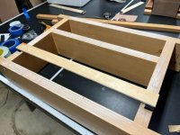
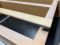
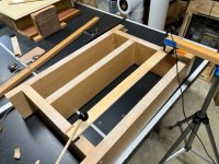
Then it occurred to me to make a 1-D panel (i.e. beam) and test that instead. I'm still playing around with different arrangements but the basic idea is shown in the images below.
First I have a frame to which the damping material and "beam" sample are attached as shown in the first two images. The span of the beam is about 50 cm. Then, similar to my panel tap test, I place the mic close to the beam (say 2 mm) somewhere along it's length, and tap it using my mallet at another spot on the beam. Presently I'm tapping and mic-ing about 3 cm from the inside edge of the damping material. This excites several beam bending modes, especially the 2nd, 3rd and 4th about equally, it seems.
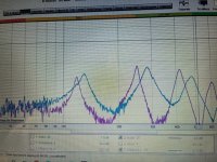
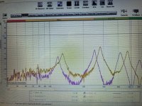
As in my other panel tap test, I monitor the mic using he RTA function in REW. The height and width of the resonance peaks should give an good indication of the effectiveness of the damping material. High narrow peaks are indicative of low damping, low wide peaks indicative of high damping.
In addition, the frequency at which the peaks occur, give an indication of the amount of constraint the damping material adds. The lower the frequencies the more closely the termination is like a simple support, while the higher the frequencies the closer the termination is to a clamped support.
The first results below compare 3M indoor foam (purple) to EPDM foam (blue). I have to admit I thought the difference would be more dramatic. But in any event the peaks are lower and wider for the EPDM than the 3M Indoor foam, apparently confirming that it is better damping and only slightly more constraining.
The second results below compares the Indoor foam (same as the first) with Sorbothane (orange line) shore 30, 3 mm thick x 12 mm wide. Interestingly, the Sorbothane, which is touted as high damping material, performs only slightly better (maybe!) than the Indoor foam, which I consider poor. Perhaps it was a poor choice of Sorbothane hardness or thickness, or perhaps this is not the intended configuration for using Sorbothane, but the result is not impressive.
I'm not settled on exactly this test methodology. That is, a different span or different tapping and mic-ing points might be somehow better. Also, these results are really only strictly applicable to a specific beam material, since a different beam will have a different impedance. But I think this general method offers a quick way to assess various end damping materials and dimensions with only a small amount of material. Now to find more materials to test.
Eric


Apparently using an abstract infinite plate simplifies the math and gives a ‘close enough’ result. More here https://www.hambricacoustics.com/In19_inf_panel.pdfOdd, it seems the quote button is available lately only for the second to last post, but not the latest post.
I have always been a bit skeptical about this finite aperture concept. It kind of seems like someone realized they couldn't do the math for the real case of a finite panel, but could do the math for this imaginary concept of an infinite panel with a finite aperture. So they proceeded with the analysis, perhaps for a fun exercise, just to see what would come out. And, lo and behold, the analysis predicted acoustic radiation below coincidence for this imaginary construct of infinite panel with finite aperture. And they thought, "hey we know that a real finite panel has acoustic radiation below coincidence, and this aperture idea predicts acoustic radiation below coincidence, so it must be a good model of a real finite panel"!
I am probably wrong but the whole thing seems a bit weak to me. It totally ignores presence of natural frequencies! How can that possibly be right?
Eric
Burnt,
Thanks for that link. I have not read that one, though Hambric is one of my favorites. He actually works in the same lab where I did my own graduate work (though I was not in Acoustics), so I have a special affinity for his papers. And I had to laugh at Figure 1, the "Recreated" back of the envelope!
No doubt he shows some utility to the infinite plate abstraction, but I'm holding on (for now!) to my skepticism of the finite aperture part! Especially for the low end of the frequency range.
I've seen this term mobility before but not really understood it, apparently it's the inverse of impedance?
Eric
It’s a really nice paper and I like his humour. Amazing that Hambric works in your lab! Yes I understand your wish for a more precise and relatable physical model my only fear is that the math will be beyond me. That of course is entirely my problem.
Regarding mobility my understanding is that it is the inverse of impedance when impedance is considered as a form of resistance. I think the problem for me is that I think of it more in terms of a load as in a reactive load else why would some of the energy be reflected. I obviously have much more to learn.
Burnt
Last edited:
Me too. I'm counting on Christian and Paul to figure that out for us.my only fear is that the math will be beyond me.
Eric
Oops, I was wrong earlier about this k wavevector:

it looks a lot like wave speed but the the B/mu is inverted to mu/B.
it looks a lot like wave speed but the the B/mu is inverted to mu/B.
Hello EricBurnt,
Thanks for that link. I have not read that one, though Hambric is one of my favorites. He actually works in the same lab where I did my own graduate work (though I was not in Acoustics), so I have a special affinity for his papers. And I had to laugh at Figure 1, the "Recreated" back of the envelope!
No doubt he shows some utility to the infinite plate abstraction, but I'm holding on (for now!) to my skepticism of the finite aperture part! Especially for the low end of the frequency range.
I've seen this term mobility before but not really understood it, apparently it's the inverse of impedance?
Eric
Thank you for the explanation about the "new" feature. Progress never ends?
I like your "anti-xylophon".
Yes mobility is the inverse of the mechanical impedance (a bit like the admittance in electricity). I have seen it in different papers about instrument soundboard like the thesis about the piano soundboard.
Extract of fig1 of M Hambric's paper :
Mobility Ym = v/f = 1/(8sqrt(Bµ) = 1/Zm. D for B, µ=rho.h standard!
I haven't found in the paper many new information. It explains the reason the mobility of an infinite panel is useful for a finite plate.
The good input is the mobility at the edge of a semi infinite beam which is not the one of the infinite beam (see before the short exchange about the impedance at the edge of a plate compare to the infinite plate value).
The paper also explain the propagation in a beam which seems different the one of a plate. To see more in detail but if so, the "anti-xylophon" might be no reflected the panel behavior?
Christian
I found this thesis MULTI LAYER VISCO-ELASTIC DAMPING DEVICES. It contains some introductions to the visco-elastic materials. Browsing yesterday on diyAudio I discover a brace technique for loudspeaker enclosure made of 2 members linked by a visco-elastic material working in shear force as shown in the thesis. Don't know if it can apply to DML but it is a step in this domain.
Christian
Christian
- Home
- Loudspeakers
- Full Range
- Effect of Boundary Conditions on the Ringing of DML Speaker Panels