Hi,
you already have three posters telling you that 3pair on +-75Vdc is not too clever with speaker loads below 4ohms.
The drivers look as though they are ticking over at about 13mA to 15mA. A big sink will help them out.
The base resistors are a bit high. They will pass about half an amp peak transient current into a 4ohm speaker load. That will drop about 1.7V. This will lead to increased distortion.
I have used a minimum effective impedance on fast starting transients of about 0.35*nominal impedance, i.e.1r4.
AndrewT, thank you for replying. You are right 3 pair is not enough. I am just stuck with the power supply and chassis of the old amp to work with. Having had this amp since 1984 without output issues means that I use it conservatively with loads of 4R and up.
My drivers are on the output heatsinks and since the copper heatsinks are the rail buss' I get pretty good heat transfer. (No insulators) I am sure this helps a little.
Am I correct that you are suggesting 1R4 for the output base stoppers? I didn't understand your math. Can I get a simpler explanation? For my simple mind that is!!!🙂
If 1R4, why not 0R0?
Thanks, DonS
Hi,
many amplifiers use 0r0 for base stopper resistors.
That then leaves no leeway for eliminating oscillation.
Leave space for low value base stoppers. I have had success with 1r0, but then I did not retest the amp with a shorting link across the stopper to see what difference it made.
The minimum impedance of a speaker is often assumed to be Re and Re~=0.7*nominal impedance.
There is a body of opinion that the effective impedance presented by a speaker is much below Re and some designers are stating minimum values around 0.35*nominal impedance.
That's where the 1r4 comes from, but this is not a resistive load.
I suppose I should have said 1.4ohms.
Now if you use that minimum impedance and calculate the maximum transient current that could flow to the load you have something approaching 50Apk into a 4ohm speaker. (that's part of the reason I never recommend low impedance speakers).
This is a transient peak, not the peak value of a continuous sinewave signal.
Divide the output signal by the transistor gain and the numbers of pairs and you get the base current drawn from the drivers. They are operating in ClassAB and feeding through the base stoppers. Similarly when the driver is sending 400mA to 500mA out to the output pairs it draws about 5mA to 10mA from it's base, but the resistor here is only 22r and that drops about 0.2V. This may be tolerable.
Thanks, AndrewT! I think I have it now. A 4R0 speaker load as a worst case becomes a 1R4 load. 0.35 as a factor sounds like Otala! Which leads to a voltage drop on each base resistor which you stated as 1.7V, based on 50A, beta of 40, and 3 pairs of outputs, correct?
Why is the voltage drop causing increased distortion? Is there a rule of thumb regarding what is an exceptable target for this drop? If we are to factor in stablity that is.
Thanks, DonS
Why is the voltage drop causing increased distortion? Is there a rule of thumb regarding what is an exceptable target for this drop? If we are to factor in stablity that is.
Thanks, DonS
Don,
I'm pretty sure Sanken still make multiple emitter devices rated to more than 200W. If so, and check their site, I'd say you could get away with using the present power supply with these devices as long as the load does not drop below 3R. They are not quite worthy of two lesser pairs, such as the MJL21193/43 series, but three pairs should effectively take it to near five pairs of the smaller devices. This is not quite what is suggested here, but given your constraints and the present history of the amp, it should be OK if you don't belt it too hard.
Another factor to consider here with multiple pairs is matching. Like devices should be closely matched in power amplifiers, and as the pairs increase in number, the likelihood of matching from a given batch drops like a stone. Three pairs is achievable, four is tricky, five is very difficult. You'd need around 100 devices from the same batch to get even two braces of matched fives, in my experience, though I match for both Vbe and beta, both specified at the quiescent current. To soften the matching requirement, you can increase the emitter resistor to around 0R33 or even 0R47; this also improves current matching at full power and thus improves reliability since there is no current hogging.
If the amp is 1984, check the filter caps are not dried out, as these components do progressively fail, particularly if they get hot.
Hugh
AKSA said:Don,
I'm pretty sure Sanken still make multiple emitter devices rated to more than 200W. If so, and check their site, I'd say you could get away with using the present power supply with these devices as long as the load does not drop below 3R. They are not quite worthy of two lesser pairs, such as the MJL21193/43 series, but three pairs should effectively take it to near five pairs of the smaller devices. This is not quite what is suggested here, but given your constraints and the present history of the amp, it should be OK if you don't belt it too hard.
Another factor to consider here with multiple pairs is matching. Like devices should be closely matched in power amplifiers, and as the pairs increase in number, the likelihood of matching from a given batch drops like a stone. Three pairs is achievable, four is tricky, five is very difficult. You'd need around 100 devices from the same batch to get even two braces of matched fives, in my experience, though I match for both Vbe and beta, both specified at the quiescent current. To soften the matching requirement, you can increase the emitter resistor to around 0R33 or even 0R47; this also improves current matching at full power and thus improves reliability since there is no current hogging.
If the amp is 1984, check the filter caps are not dried out, as these components do progressively fail, particularly if they get hot.
Hugh
Huge,
I strongly agree with your mark about the emitter resistors. This item of increasing slightly the resistance according to the number of output devices used usually it is omitted from the most people. I believe most of them they don't know this subject. My practice it is as follows: From my experience, if i have 4 pairs of output devices i use a single E.F. driver stage and 0,22R resistors without matching devices (simply i select them from the same batch in the packing). For 5 pairs i match the devices and i use also 0,22R resistors but i douplicate the driver stage by seperating it in one predriver and in one driver stage (this called from some people triple darlington arrangement). For 6 pairs and above except the previous i increase the resistors to 0,33R for the reasons that you refer and for a better thermal dynamics management. The bigger the value of emitter resistor the better the thermal feedback in output devices. According IMHO all of these. I have checked this item thorougly and i have ascertained that from +/-70Vpp supply and above, the use of 0,22R resistors in emitters it is risky. The thermal runaway danger lurked in each moment!
Fotios
Hi Fotios,
Thanks for the post. Yes, your experience is the same as mine, and while the larger emitter resistors reduce the transconductance of the output stage, the more pairs you use, the more it increases to compensate! And these resistors are inside the feedback loop, so their resistance is reduced to near zero for high damping factor.
The other advantage is that since the bias voltage across the emitter resistor, from Boltzmann's constant, is around 26mV, then with a larger resistor the bias current is reduced for Class AB. This cuts the quiescent; if you have five output pairs, reducing each pair to 55mA keeps quiescent to 275mA, which is 41W at idle, around half if you use low value emitter resistors.
An interesting option can be used for six or eight output pairs. By using two drivers, with separate bias control for each, you can reduce the matching to triples or quads, which saves more money than it costs with the extra driver!
Cheers,
Hugh
I understand some of the compromises I am making with 0R235 emittor resistors. The original amp had 0R1's! I have designed a low feedback FE and also plan to try and take the FB from the drivers not the outputs. In that case the emitter resistors need to be as low as reasonably possible.
Any thoughts on my changing the FB point?
I could have reused the old Sankens, as there was nothing wrong with them. I wanted to update the devices so replacements would be available. IMHO the 2119x devices are superior to the devices removed, from a SOAR point of view. It was also the first time I saw a data sheet with distortion spec's for audio use.
The original ckt also had what I thought was a strange value for the driver's emitter resistor. (33R2) What are the upsides and downsides to this low value?
Thanks, DonS
Don S said:I understand some of the compromises I am making with 0R235 emittor resistors. The original amp had 0R1's! I have designed a low feedback FE and also plan to try and take the FB from the drivers not the outputs. In that case the emitter resistors need to be as low as reasonably possible.
Any thoughts on my changing the FB point?
I could have reused the old Sankens, as there was nothing wrong with them. I wanted to update the devices so replacements would be available. IMHO the 2119x devices are superior to the devices removed, from a SOAR point of view. It was also the first time I saw a data sheet with distortion spec's for audio use.
The original ckt also had what I thought was a strange value for the driver's emitter resistor. (33R2) What are the upsides and downsides to this low value?
Thanks, DonS
With only three pairs of output devices, 0.235R will be fine. At peak output currents they will be dropping well over a volt each, which is more than enough to ensure adequate current sharing.
With regards to bias current thermal stability, it all depends on how much bias current you can run.
The higher the bias current, the greater the stability. Even OR1 would be fine with ~100mA per device.
I’m building an amp with +/-80V rails, 15 pairs of devices and 0.2R emitter resistors, but it dissipates a lot at idle.
If you want to take the NFB from the driver stage, then you probably would want a high bias current to keep distortion low. How big are your heatsinks?
BTW, 3 pairs of MJ2119X devices on +/-75V rails is still very low, even for 4 ohm loads. If you’re going to replace the supply filter electrolytic capacitors, don’t add a lot more (if any) capacitance than what the amplifier originally had.
Cheers,
Glen
G.Kleinschmidt said:
With only three pairs of output devices, 0.235R will be fine. At peak output currents they will be dropping well over a volt each, which is more than enough to ensure adequate current sharing.
With regards to bias current thermal stability, it all depends on how much bias current you can run.
The higher the bias current, the greater the stability. Even OR1 would be fine with ~100mA per device.
I’m building an amp with +/-80V rails, 15 pairs of devices and 0.2R emitter resistors, but it dissipates a lot at idle.
If you want to take the NFB from the driver stage, then you probably would want a high bias current to keep distortion low. How big are your heatsinks?
BTW, 3 pairs of MJ2119X devices on +/-75V rails is still very low, even for 4 ohm loads. If you’re going to replace the supply filter electrolytic capacitors, don’t add a lot more (if any) capacitance than what the amplifier originally had.
Cheers,
Glen
Glen, I am using about 100mA per device now and the sinks will not take much more without getting too hot.

How much more bias would you recommend if I use the drives as my FB point.
I know 3 pairs of outputs are too little. I am stuck with it for this project though. I don't know how the Sankens held up for 20+ years myself!
The power supply has 10,000uF per rail, per channel. I was thinking of upping it to 22,000uF. Physical size is the biggest problem! I was thinking of using 80V caps in order to increase the capacity. 80V caps on a 75 volt rail scares me though. If I go with 100V caps I cannot make a value change. Should I risk the 80V caps?
What about the (low) R value of the driver emitter resistor that I mentioned above? Why? What benefits? What drawbacks?
Thanks, DonS
How high will the rail voltage go if the supply rail fuses blow?
How high will the supply rails go if the mains supply goes to maximum tolerance?
Would any combination of these conditions cause the caps to explode?
How high will the supply rails go if the mains supply goes to maximum tolerance?
Would any combination of these conditions cause the caps to explode?
AndrewT said:How high will the rail voltage go if the supply rail fuses blow?
How high will the supply rails go if the mains supply goes to maximum tolerance?
Would any combination of these conditions cause the caps to explode?
The supply rails have no fuses!!!!!!!!!!!
 :rip:
:rip:This is not my idea! Only mains fuse and over temp cutout!
Line in today is 119VAC
No load 75V Rails
Rails loaded with 350mA = 73V Rails
I know it is a close call! It is possible the rails would spike to about 85V! Is there any cushion to the voltage rating? At 80.1V does it go poof and let the magic smoke come out? The originals are 100V rated, but because of their physical size I would need a lower voltage rating to increase the values. Scary ain't it?
Thanks, DonS
I don't expect any electrolytic to go poof because it is 0.1% overvoltage.
But the risk of failure increases as maximum working voltage is approached and increases rapidly once max WV is exceeded.
It becomes a life consideration. Will it last 10mins, or 10hours, or tens days, or ten weeks, or ten months? I suspect you would not be happy with any of those projected lifetimes, especially considering that it may not just be the caps that you lose.
Now put in four capacitors and you increase the risk of failure by a factor of four (statisticians will tell me otherwise, but you get the jist).
AndrewT said:I don't expect any electrolytic to go poof because it is 0.1% overvoltage.
But the risk of failure increases as maximum working voltage is approached and increases rapidly once max WV is exceeded.
It becomes a life consideration. Will it last 10mins, or 10hours, or tens days, or ten weeks, or ten months? I suspect you would not be happy with any of those projected lifetimes, especially considering that it may not just be the caps that you lose.
Now put in four capacitors and you increase the risk of failure by a factor of four (statisticians will tell me otherwise, but you get the jist).
Yes I know what you are saying! I would live with 2 years and just think of them as replacement batteries then!!!
I still want someone to explain why the original amp had such a low emitter to emitter resistor on the drivers!
Anyone care to comment?
Thanks, DonS
P.S. I will post the full amp schematic if someone is curious? It does work and doen't sound too bad! I don't like to evaluate my own designs!
AndrewT said:I don't expect any electrolytic to go poof because it is 0.1% overvoltage.
Now put in four capacitors and you increase the risk of failure by a factor of four (statisticians will tell me otherwise, but you get the jist).
More caps = higher capacitance = lower ac ripple voltage. I would be in favour of this approach for reasons of lower supply impedance and longer capacitor life.
Glen, I am using about 100mA per device now and the sinks will not take much more without getting too hot.
How much more bias would you recommend if I use the drives as my FB point.
I know 3 pairs of outputs are too little. I am stuck with it for this project though. I don't know how the Sankens held up for 20+ years myself!
The power supply has 10,000uF per rail, per channel. I was thinking of upping it to 22,000uF. Physical size is the biggest problem! I was thinking of using 80V caps in order to increase the capacity. 80V caps on a 75 volt rail scares me though. If I go with 100V caps I cannot make a value change. Should I risk the 80V caps?
What about the (low) R value of the driver emitter resistor that I mentioned above? Why? What benefits? What drawbacks?
Thanks, DonSreliable for so many years with only 3 transistor pairs – the rail
OK, I was expecting the capacitance to be rather low, and at 10,000uf it is indeed. This explains why the amp has been reliable for so many years with only 3 transistor pairs – the rail voltage will droop significantly if the amplifier is driven hard into a low impedance load, easing the strain on the transistors.
More capacitance will enable the amplifier to deliver high power for a longer duration and make it easier to blow. With 3 transistor pairs, 10,000uF is probably a good compromise. That's what I would stick with.
Unfortunately, with regards to bias current, you’re pretty much stuck with what you can run with your heatsinks. Personally, I would take the NFB from the output stage and let that take care of the distortion.
I suggest that you build it as you have planned, crank the bias current up as high as practicable and listen to it. If it sounds good enough, leave it as it is 🙂
Cheers,
Glen
I missed that.G.Kleinschmidt said:
OK, I was expecting the capacitance to be rather low, and at 10,000uf it is indeed. This explains why the amp has been reliable for so many years with only 3 transistor pairs – the rail voltage will droop significantly if the amplifier is driven hard into a low impedance load, easing the strain on the transistors.
More capacitance will enable the amplifier to deliver high power for a longer duration and make it easier to blow. With 3 transistor pairs, 10,000uF is probably a good compromise. That's what I would stick with.
Unfortunately, with regards to bias current, you’re pretty much stuck with what you can run with your heatsinks. Personally, I would take the NFB from the output stage and let that take care of the distortion.
I suggest that you build it as you have planned, crank the bias current up as high as practicable and listen to it. If it sounds good enough, leave it as it is 🙂
Cheers,
Glen
It mimics what Sugden designed into the P128 monoblock amps.
Two small EI transformers (guessing 175VA each) feeding 2pair of 4700uF 80V caps. Rail voltage when fully biassed is +-71Vdc (+8V on the Vamp stages) the two pair lateral FETs manage 195W into 8r but the rails collapse to +-52Vdc on a 4ohm load and obviously even lower when the effective impedance falls below nominal. It looks like a deliberate design decision to use high transformer regulation and low smoothing to protect the output stage. Makes for a fairly good 8ohm amplifier.
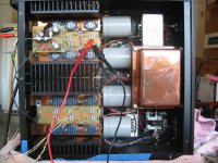
Thanks all for your inputs. I figure I would include a picture of California engineering at it's finest?
1200W power transformer! That's a pack of cigarettes on top for reference. As you can see the caps are wedged against the transformer. (They also touch the bottom of the case.) They bolt directly to the copper buss bars which supply rail voltage to the drivers and output devices. IMHO not a bad way to get power to the devices. (No insulators either!) The down side is no rail fuses!
Later amps had a smaller transformer and (larger) 15,000uF supply caps.
Thanks, DonS
Attachments
AndrewT said:I missed that.
It mimics what Sugden designed into the P128 monoblock amps.
Two small EI transformers (guessing 175VA each) feeding 2pair of 4700uF 80V caps. Rail voltage when fully biassed is +-71Vdc (+8V on the Vamp stages) the two pair lateral FETs manage 195W into 8r but the rails collapse to +-52Vdc on a 4ohm load and obviously even lower when the effective impedance falls below nominal. It looks like a deliberate design decision to use high transformer regulation and low smoothing to protect the output stage. Makes for a fairly good 8ohm amplifier.
Would make a good 4 ohm amplifier for HiFi use too, as a high continuous power output isn't really a requirement. This isn't such a bad way to design an amplifier. With the high voltage rails, you have a high transient power output capability giving a high amount to headroom to avoid clipping on the occasional peak, without the need for a humungus output stage.
Cheers,
Glen
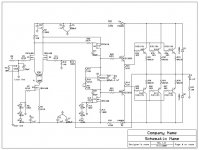
Here is the full circuit below. It works, and think it sounds good too! I have used fets in the voltage amplification spots because they are voltage to current devices. Bipolars in the current gain stages because they are current amplification devices.
I took the original 5 stage amp and reduced it to 4. I spec'd very robust mosfets to handle the voltages and currents needed to do this. There is 9mA running through the LTP and 20mA though the VAS.
The only issue I would really like to solve at this moment is that the initial DC offset is -350mV. This drops to -100mV in ~6minutes. After about 20 minutes It will maintain an offset of +- 20mV under all conditions.
Suggestions to reduce initial offset?
Please take a look and feel free to make suggestions for improvement.
Thanks, DonS
Attachments
- Status
- Not open for further replies.
- Home
- Amplifiers
- Solid State
- EF Output Stage