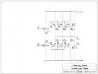
I have included my output stage for others to look at, spice and comment about. I am looking for stability, current drive, and reliablity! I am also very curious to know the F3 of this circuit! It would help if I knew the input current needed to provide +25 and -25 amps at the output. Also the SOAR. Please feel free to comment.
I am looking at driving a 3.5 ohm load of a dynamic speaker. 2 ohms would be even better!
Thanks, DonS
I am looking at driving a 3.5 ohm load of a dynamic speaker. 2 ohms would be even better!
Thanks, DonS
Attachments
Looks good Don,
You could string a 220nF cap across the emitters of the drivers for charge suckout, but this will fly very nicely.
If you go for 25A output from each half, this will be around 8A from each device, and at this current assume a gain around 40, which will require 200mA for each OP device, and thus a total of 600mA from the driver.
At 600mA you would have a gain around 80 from the driver, and this needs 7.5mA of drive at the base.
To allow for a reliably functioning VAS and Vbe multiplier, you should run about double this current as VAS bias, so 15mA should do it. Your 100R of inter-emitter resistance should be about right for this configuration, which is also known as the Self Type II EF.
Hugh
Hi,
the 3pair on 75Vdc will drive 8ohm to 60degree phase angle with Tc<=60degC at the limit of the DC SOAR.
However 4ohm 30degree reaches the same DC SOAR limit.
increasing the load phase angle to 60degrees takes the output stage to 163% of the DC SOAR.
I have no data for the transient capability of these transistors.
Reactive 3ohm loading will increase the stress on the output devices even higher.
I have guessed that the drivers have an second breakdown knee at about 40V. These will survive better than the output devices.
Taking the same phase angles and using output current gains of 58/40/35 for loads of 8/4/2 ohms the drivers stay within my estimate of DC soar upto 70degC.
Hugh, they are very tough devices, but Andrew has a point on load phase angle . There have been a few threads on this subject in the foprum and if you want to go to 3 Ohms (some will want to go to 2 . . . ) and cater for tough loads, 3 output pairs on a 75V rail may not be enough.
BTW there was a nice expose on this subject a few months ago by Keith howard in Hi-Fi News (I think it was this publication). I was really surprised at how bad some speaker loads are - worst was the Finial electrostatic. I'd call it an Amp killer!
I wonder if the drive requirements (15mA) from the VAS on this design are'nt a bit high, especially for 4 Ohms which could lead to non-linearity issues.
🙂
I agree that the MJ21193/4 are tough devices that should survive even PA use.AKSA said:these are extremely tough devices. Three pairs at 75V will be fine down to 3R.
Are you saying OK on 3r0 or on 3ohm reactive?
High phase angles take these devices well outside the DC SOAR at the device temperatures I quoted.
It's a pity Onsemi has not updated the datasheet giving more information on transient ability. It may be that their reputation is rightly so and could be due to a high factor between DC and 100mS or 10mS peak currents.
If the output devices do turn out to be so robust that they can drive a severe 4ohm load, then the little bit of spare in the drivers will be used up and the drivers become the bottleneck.
Hmmm. OK, Don, build it and see how well it works.
If it doesn't work too well, or easily blows up, use four pairs.
Simple!
Cheers,
Hugh
If it doesn't work too well, or easily blows up, use four pairs.
Simple!
Cheers,
Hugh
I personally like the Triple Darlington (as called by Leach) arrangement. Basically, this is just a "pre-driver" stage driving the drivers. The main advantage is it allows the drivers to always have current flow - which reduces crossover distortion.
http://users.ece.gatech.edu/~mleach/lowtim/output.html explains further.
http://users.ece.gatech.edu/~mleach/lowtim/output.html explains further.
AndrewT said:
I agree that the MJ21193/4 are tough devices that should survive even PA use.
Are you saying OK on 3r0 or on 3ohm reactive?
High phase angles take these devices well outside the DC SOAR at the device temperatures I quoted.
It's a pity Onsemi has not updated the datasheet giving more information on transient ability. It may be that their reputation is rightly so and could be due to a high factor between DC and 100mS or 10mS peak currents.
If the output devices do turn out to be so robust that they can drive a severe 4ohm load, then the little bit of spare in the drivers will be used up and the drivers become the bottleneck.
With 75V rails, a woefully inadequate 3 parallel pairs of output devices will never endure any decent amount of continuous PA use into a 3 ohm load without expiring prematurely.
On semi haven’t published any transient SOA charts for these devices, but a good rule of thumb for building robust output stages with these devices, which will be tollerant of a fair amount of abuse, is to use as many devices as necessary to enclose the reactive load line inside the non-temperature de-rated 1sec SOA. Assuming a peak output swing of 65V with 75V rails, you need no less than 7 pairs of devices to enclose a 3 ohm / 45-degree reactive load line inside the non-temperature de-rated 1 sec SOA.
The MJL2119* devices are robust parts, but they are not indestructible. I’ve blown enough up to know.
I don't believe Leach's argument. I think it is flawed.jaycee said:I personally like the Triple Darlington (as called by Leach) arrangement. Basically, this is just a "pre-driver" stage driving the drivers. The main advantage is it allows the drivers to always have current flow - which reduces crossover distortion.
http://users.ece.gatech.edu/~mleach/lowtim/output.html explains further.
Adding a pre-driver does not influence the validity of his claim that preventing switch off is the same as ClassA.
I do agree that the pre-driver is particularly useful for low impedance loads. If the driver and output are kept in the high gain range of currents then a To92 small signal device can perform as pre-driver. But if the outputs and/or the drivers are asked to operate in a low gain current range then a medium power device may be necessary.
I was beginning to think I was being over-cautious. I have been told that before, but I don't want any of my amps blowing up and I certainly would not want my advice to lead to a members' blow up.G.Kleinschmidt said:............ Assuming a peak output swing of 65Vwith 75V rails, you need no less than 7 pairs of devices to enclose a 3 ohm / 45-degree reactive load line inside the non-temperature de-rated 1 sec SOA.
The MJL2119* devices are robust parts, but they are not indestructible. I’ve blown enough up to know.
I would have gone to 4 or 5pair for +-75Vdc and 4ohm 60degree phase. 3ohm 45degree phase is about 6% more stressful.
The decision on 4 or 5 pair would be made on the basis of predicted temperature and heatsink size.
AndrewT said:I was beginning to think I was being over-cautious. I have been told that before, but I don't want any of my amps blowing up and I certainly would not want my advice to lead to a members' blow up.
I would have gone to 4 or 5pair for +-75Vdc and 4ohm 60degree phase. 3ohm 45degree phase is about 6% more stressful.
The decision on 4 or 5 pair would be made on the basis of predicted temperature and heatsink size.
I don't think that I am being over cautious here. +/-65V peak into 3 ohms gives 700W rms. That's a pretty serious power amplifier. Pushed hard, it will generate a lot of heat, so you don't want to skimp on a few output pairs, especially so, considering the fact that they are a small cost in comparison to the heatsink (not to mention the rest of the amplifier).
The rule of thumb (which I am comfortable with) I gave basically boils down to one pair per of devices per 100W.
Cheers,
Glen
Hi GK,
I am not disagreeing with you. It was nice to see some support for my view that 3pair was pushing the envelope (or is that locus).
I am not disagreeing with you. It was nice to see some support for my view that 3pair was pushing the envelope (or is that locus).
Don S said:I have included my output stage for others to look at, spice and comment about. I am looking for stability, current drive, and reliablity! I am also very curious to know the F3 of this circuit! It would help if I knew the input current needed to provide +25 and -25 amps at the output. Also the SOAR. Please feel free to comment.
I am looking at driving a 3.5 ohm load of a dynamic speaker. 2 ohms would be even better!
Thanks, DonS
MJ21193-MJ21194 are some delicate. According the SOA given by ONsemi, with Vce=75Vp can sustain as much 3A each (VI phase shift due to reactive loading may included in these 3A). The rated current in output for 3Ù load it is thus 25Ap. Thus you need at least 8 pairs in output to be sure. If you use a VI limiter circuit (fixed at 600VA +/-45deg max shift) you can use 6 pairs. Also the devices must be matched as for the beta for same Ic in each. Or else the output devices their "meet its fate" very soon
 Also you need either enormous heatsinks or forced air cooling. And don't forget a thermostat on 85degC for safety. Trust me. I have checked thorougly these devices. Don't trust SPICE for 150Vpp. It supposes ideal models and in practice this failed. Up to 80Vpp SPICE it is by 80% correct in prediction. For so much supply, i preffer the beast MJ15024-MJ15025 with predrivers the MJE15032-15033 and main drivers the beast but sweet MJ15020-15021 (ft=20MHz). Remember that in a high power level audition, the S/N increased amazingly and the THD it is extinguished because the dynamics of output power and the noise of fans disappears. Summarising your priority it is the armouring of output. The rest, after this.
Fotios
Bonsai said:I wonder if the drive requirements (15mA) from the VAS on this design are'nt a bit high, especially for 4 Ohms which could lead to non-linearity issues.
🙂
Absolutelly true and checked. The VAS needs at least 20mA and the long tailed pair (if used only one) needs 3 to 4mA for uniformity (linearity) of the two portions of voltage swing. This can be checked only by applying square wave in input.
Fotios
Don S said:I am also very curious to know the F3 of this circuit!
Thanks, DonS
The frequency response it is under the overal design and the rest of parts used. As for the transistors given:
MJ21193-21194: Ft=4MHz (more than enough in EF output stage)
MJE15032-15033: Ft=30MHz (excellent!)
Fotios
Don S said:I have included my output stage for others to look at, spice and comment about. I am looking for stability, current drive, and reliablity!
Thanks, DonS
One more thing Don S.
Have you examine the difference between MJ21193-21194 and MJ15022-15023 or MJ15024-15025?
As for the Ft all have the same=4MHz max.
The only difference it is that the 2119x have characterized THD and better gain linearity. The hFE it is almost the same for the three types. From audition tests, the 2119x indeed heared a little better from MJ1502x.
Fotios
Just to add to Glen's point, I'm going from 5 pairs of output devices to 8 pairs to cater for reactive load at 3 Ohm - this after doing a lot of simulation work over the last few months. Building a big amp that is even moderatley load tolerant (i.e. reactive load) requires a lot of output silicon.
BTRW I use a triple to overcome the the VAS loading issue with pre-driver and driver running class A.
BTRW I use a triple to overcome the the VAS loading issue with pre-driver and driver running class A.
With adequate mounting and heatsinking I would not hesitate to run three pair of TO-3 MJ2119X on ±75 into a 3R load.
I have a ±80V Leach output stage that has been running a 1R0 load for about 18 years now. One pair of MJ15022/25 driving nine pair of same for outputs, 2N3583/6421 for pre-drivers, BeO2 insulators.
I did have a Leach fail after 25 years with only 3 pair of MJ15011/12 driving a 2R0 load with ±63V rails. The owner of that system would on occasion drive it at least 6dB into clipping and activate the current limiter circuit (nasty sounds). The amplifier has gone through three sets of electrolytics in the same period of time.
Thank you all for the information!
I am doing a total redesign of an old amp I already have. I am limited to only 3 pairs of outputs on the heat sinks. I never had a driver or output failure with the old amp. MJE15030, 31 drivers and Sanken 2SA909, 2SC1586 outputs. The old amp doesn't have any current limiting either. The manufacture spec'd operation down to 1R5 loads at up to 1000W outputs. Obviously not RMS!
I don't intend to use it for sound reinforcement or a shaker table!! If that was the case I would probably have spec'd 12 pairs per channel!
My biggest concerns are bias stability, freedom from self-oscillation, and not oscillating into typical speaker loads.
So the big question now is the resistor values in the stage. I have guessed at them and they work! However they probably can be adjusted for improved performance. Also I am thinking about taking the loop feedback from the middle of the driver emitter resistors. I bet that some of you wondered why I used 2.
I plan on leaving the output emitter resistors at 0R235 because with my heat sinks and unmatched outputs I believe that they are a good tradeoff for efficiency, bias stability, and sweet spot voltage at my idle bias. (23mV across the output emitter resistors) This as suggested by many people.
Please let me know what you think can be improved!
Thanks, DonS
- Status
- Not open for further replies.
- Home
- Amplifiers
- Solid State
- EF Output Stage