I’ve seen many baffle-less speakers with no edge treatment. I would think some kind of round-over and rocket nose back shaping would make a difference but apparently it’s too much bother. I know di and bipoles are a bit different but they still have edges. Actually, they have edges all over the place.Hi, roundovers need only be as big as fits: if your driver is 1" and its 5" sized baffle/box, use 2" radius and start it right at the tweeter. If you have 2" baffle for the 1" source, 1/2" radius is as big as fits and pretty much as effective. If you have no baffle at all, no radius fits, and thats best you can do and almost the same performance as the previous two. If you have large flat area around a driver, you'd need very big radius roundovers. The baffle supports long wavelength so high radius is needed to mitigate, slap on roundovers and it gets bigger, so interference gets lower in frequency. Although, you could make the baffle approach room dimensions and any edge diffraction related backwave is mixed into all kinds of reflections from room boundaries and objects.
So, either very big structure around a driver, or as small as you can have. The smaller the sttucture isnthe smaller roundovers need to be for very little diffraction related issues in listening window response.

for the wave to engage it, the large radius on the front, the small radius on the side I think
Asymmetrical shapes would be my suggestion. Shapes bounce back. Even with rounding an symmetrical shape can bounce-I guess if it is very wide that can get around it (pun intended).To spice up my boring 2 way build I am going to try some 3d printed edge diffraction pieces to see what difference they might make.
I will be starting with this aerofoil/teardrop shape. This is a pretty small one but I can make it wayyyyy bigger which is probably what I will try next.
Does anyone else have a shape they would like me to test? Let me know. Let's do some science!
I am waiting on parts to test a chiral aperiodic monotile (it is a non-repeating shape even when reflected). https://arxiv.org/pdf/2305.17743
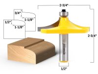
Show me a picture of the profile you're talking about. I'll model it and run ithere's one.
a multi-radius round over -- in other words, a parabola -- might deliver aspects of large radius round overs without involving an overly thick front baffle.
if you could model a first approximation -- cut by a commercial large thumbnail router bit -- as well as a comparable mathematical parabola that might be instructive.
While the notion revolves around a parabolic profile the implementation depends on the actual bit that can be procured and managed by the carpenter. Arthur Jackson has shown one. Here is another:
Were there a CNC available to me that could cut a specified parabolic shape something more particular to driver and front baffle...
Were there a CNC available to me that could cut a specified parabolic shape something more particular to driver and front baffle...
Attachments
Interesting. I'll have to find this. Thanks
Not the document you are looking for but read page 10. Earl stated clearly the radius dimension to frequency ratio ( hint: it's always the same ratio wether being center to center distance, or almost anything related to loudspeakers,...).
http://www.gedlee.com/Papers/Philosophy.pdf
While the notion revolves around a parabolic profile the implementation depends on the actual bit that can be procured and managed by the carpenter. Arthur Jackson has shown one. Here is another:
there is also one Yonico thumbnail bit larger than the one you posted.
But the depth is still only 5/8-inch, so isn't going to do as much as a 1-inch, 1-1/4 inch or 1-1/2 inch roundover bit.
That link won't open. Do you have a picture of this?Asymmetrical shapes would be my suggestion. Shapes bounce back. Even with rounding an symmetrical shape can bounce-I guess if it is very wide that can get around it (pun intended).
I am waiting on parts to test a chiral aperiodic monotile (it is a non-repeating shape even when reflected). https://arxiv.org/pdf/2305.17743
That's my idea behind the teardrop. I could be totally wrong but I think frequencies follow similar physics as fluid dynamics when it comes to flow attachment. Probably not a 1:1 but similar. I've studied fluid dynamics extensively so I will start from that basis and see what happens.for the wave to engage it, the large radius on the front, the small radius on the side I think
I'm for sure going to test this. The edges of the bare cabinet are perfect, very sharp, 90 degree edges with the drivers exactly centered. This should be the absolute worst for diffraction so it's a good starting pointI’ve seen many baffle-less speakers with no edge treatment. I would think some kind of round-over and rocket nose back shaping would make a difference but apparently it’s too much bother. I know di and bipoles are a bit different but they still have edges. Actually, they have edges all over the place.
Anything that improves it can be labeled as advantageous
B&W implemented this kind of teardrop shape.
Our estimated Dave ( Planet10) did an approximation of it on one of his box's design.
Kef's Blade are a nice example too.
Our estimated Dave ( Planet10) did an approximation of it on one of his box's design.
Kef's Blade are a nice example too.
@A4eaudio
I'm hoping the analysis will show an advantage with multiple radii, the larger of which starting things off as the wave travels along the baffle to the edge.
certainly it may not be as good as designing a deep baffle edge to take a consistent large radius curve. but that's no reason not to make the evaluation of a compromise and how close it can approach the ideal.
for context I'm generally looking at applying a 3/4" face of hardwood to a Baltic ply baffle and confining the roundover to that fascia.
particularly I'm currently contemplating fastening a piece of cherry to a birch ply FHXL cabinet.
It is known that a continually reducing radius makes effective use of space. The LeCleach horn progresses this way and it's known for continuous diffraction.I'm hoping the analysis will show an advantage with multiple radii,
See that as a good thing since diffraction may essentially need to happen, and doing it gradually has advantages.
I've taken it to the next stage here by using LeCleach horn derived shapes to demonstrate how it might look on a regular half-space baffle..

These bits might be great around a tweeter but you would need a router bit 12” across for the midrange. 😱While the notion revolves around a parabolic profile the implementation depends on the actual bit that can be procured and managed by the carpenter. Arthur Jackson has shown one. Here is another:
Were there a CNC available to me that could cut a specified parabolic shape something more particular to driver and front baffle...
Except if you make the box only ~1" (rounding bit radius) wider than the mid transducer and it's performance is great 😉 the driver beams the highs, and lows just go around the box. There is some in the middle that diffracts, but it mainly affects directivity and is uniform in that sense it's smooth response observed at any angle.
I thought it had to increase in radius as the wavelengths being produced got longer? Something like @AllenB’s profile should have nice even dispersion with reduced diffraction and reflections. But, not having a baffle at all may be better? I’d like to see some data if anyone has some links that would help. Thanks.
The longer the wavelength relative to baffle size, the less the edge and the whole construct has effect to it. Then, wavelengths about diameter of the driver are already starting to beam. So, long wavelengths are not affected, and short are not projected that much toward the edge to diffract. This small baffle leaves the main diffraction hump in response though, which narrows the pattern a bit.
If you start adding roundovers immediately beside the driver, the main diffraction hump starts to flatten out the bigger the rpubdover radius and DI decreases a bit, so could be a good thing. Overall, minimal baffle without any roundover leaves listening window pretty much clean from edge diffraction related interference. Basically the edge that radiates as secobd sound source, is so close to the driver (compared to wavelength), that it's pretty much same radiation as the driver itself.
This stuff is easy and fast to experiment in realtime in vituixcad diffraction tool.
https://github.com/christianp/aperiodic-monotileThat link won't open. Do you have a picture of this?
svg's
I second this. But one thing that does not show up in vcad is what group delay does to diffraction.This stuff is easy and fast to experiment in realtime in vituixcad diffraction tool.
- Home
- Loudspeakers
- Multi-Way
- Edge Diffraction Testing - Shapes