I went through my stuff and all projects i have on my workbench (way too many 😀 ) and found out that i have a test pcb for my amplifier and never ordered the final version. But the heater and anode power supplies are on my desk 🙂
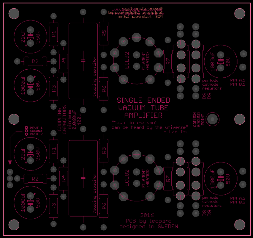
Thay is how the pch sould look like. The tube socket is on the bottom side, so that the tube sticks outside the enclosure and all the components "hang" underneath. Note that schematic does not have the R values on the board. I must have them on the paper somewhere in my mess.
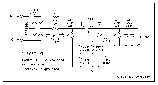
The anode power supply schematic:
Thay is how the pch sould look like. The tube socket is on the bottom side, so that the tube sticks outside the enclosure and all the components "hang" underneath. Note that schematic does not have the R values on the board. I must have them on the paper somewhere in my mess.
The anode power supply schematic:
Last edited:
Hi,
thanks! i cant see the tracks on the board. Am i missing something??I see two additional holes in the middle the ring of holes for the tube socket> what is that and how does it work?
Regards
Amit
thanks! i cant see the tracks on the board. Am i missing something??I see two additional holes in the middle the ring of holes for the tube socket> what is that and how does it work?
Regards
Amit
Last edited:
Yes 🙂. of course the UCL 82 is like 50 volts on the filament! i wonder why they chose it.and if that had a logic to it why the others didnt follow and make only UCL versions.
The ECL/PCL/UCL82 tube types are rather old ones. The UCL82 dates back to a time when DC mains grids still were common in some regions in Europe. Tube radios dedicated for usage in AC grids as well as in DC grids didn't feature a power transformer. Plate supply was derived directly from the mains via one way rectifying, the 100 mA heaters were arranged in a series chain.50V filaments comes handy if You want a PP with those tubes, need only a 220/220 isolation transformer, and the OPT's
ECL and PCL86 came to the market rather late. DC mains had all but vanished, so there wasn't any need for a UCL86. Yes, the PCL86 also was designed for series heating, but preferably in TV sets which had a very similar power supply design as those old AC/DC radios. The purpose was to save the power transformer which helped to reduce production costs and to eliminate it's magnetic stray which might have affected the CRT.
Best regards!
ok... i learnt more from you today 🙂 . bye the way someone mentioned somewhere on the site that UCLs had shorter life or more failures because the filaments were thinner based on the lower current draw. if thats true at all..what can one do about it ? A Few more questions..
should the plate voltage first reach its peak before the heaters get switched on?
how can we do this and whats the best and simplest way to soft start the filament. i had flashes on the heaters everytime i turned my little diy amp on. it was a UCL 82 and also the same happened with the ecl86 amp that i built later.
warm regards
Amit
should the plate voltage first reach its peak before the heaters get switched on?
how can we do this and whats the best and simplest way to soft start the filament.
Amit
The filament has to switch on simultaneously with the HT. Delay, if introduced, should be for the HT and NOT the heaters.
Please read this thread.
Delayed turn-on for HT
Regards,
Anwesh
My PCB two sided.There are traces of course. I showed component placement there. Two holes in a middle of tube socket is for a heater. No traces for thaton pcb. Uses a twisted pair all the way to tube socket.i cant see the tracks on the board. Am i missing something??I see two additional holes in the middle the ring of holes for the tube socket> what is that and how does it work?
No need to worry about, as usually this doesn't harm. I guess there's just some small part of the heater filaments left without the isolation coating, which, due to it's smaller heat capacity, behaves like an incandescent bulb upon powering on.... and whats the best and simplest way to soft start the filament. i had flashes on the heaters everytime i turned my little diy amp on. it was a UCL 82 and also the same happened with the ecl86 amp that i built later.
Best regards!
Doesnt that happen if you power up tube heater with a battery. It gets flashes also. Then you will burn down filament pretty soon. A constant current source would help, like a LM317 or similar. Or is it because you of like Kay Pirinha said and not the battery?
Thanks for your answers...Sometimes i noticed this flashover happening not when i first started powering my diy amp but only later on after a few days. so it kind of has confused me at the time. i had thought of putting an additional resistor in the fila ment path like 2 ohms and then bypassing it with another switch to full voltage manually.doesnt the inrush current cause this? on my German radios sometimes i saw coil in the filament circuit but usually they had nothing for inrush and the tubes never flash over. never. how do they do it? yes it has selenium rectifier( the radio) and not silicon.
Regards
Amit
Regards
Amit


- Status
- Not open for further replies.
- Home
- Amplifiers
- Tubes / Valves
- ECL86 PCB board and parts for SE amp needed