For a few bucks more one can buy much better USB boards, with better support too. I use I2SoverUSB, it's a great board at reasonable price, with very good sp/dif output too.
Hi Nino,
When I connect Amanero to dacs by disconnecting i2s resistors from AK4113 side, i get distorted crackling sound that varies with touching and moving around USB cable. Had you encountered with similar issue? I use same setup with another ES9023 based dac without such problem.
Hi terranigma,
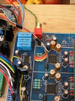
I didn't have crackling sound by moving USB cable, but when moving ground connection of i2s instead. I solved it by attaching the ground wire parallel to the other 4 i2s wires, see picture.
I also have separated the ground plane of AK4113 from the DACs, on the bottom side of the pcb (I did that mod earlier), if you didn't, I'd suggest to try that if the first tip doesn't solve the crackling.
Attachments
Hi Nino,
As I was expecting, it looks like a grounding problem. Thank you for the tip and photo. I did 4113 ground separation mod per your directions.
Btw, If you are not planning another mod, you could move VREF capacitors closer to the dacs by soldering them in place of unused decoupling caps.
I assume you modified the code by adding an extra input for I2SuverUSB that only puts AK4113 in PDN and resetting AK4399's. Since my Amanero is not isolated, I assume that I can't do similar direct connection as yours. I2SoverUSB is a superior device in this regard including spdif support.
Thank you for the tip regarding the caps.
I modified the controller program indeed, but not by adding an extra input. I simply keep AK4113 powered down, and initialize 2xAK4399 after some delay time, to be sure the USB board is been powered, just for testing purposes.
The I2SoverUSB board has an isolator, but it can't be used to switch i2s output on/off (it's not implemented, but possible). So when using the AK4113 channels too, the USB board i2s output in some way has to stop. I don't need more channels, in time I'll remove the receiver and all.
The sp/dif output of the I2SoverUSB board is very good, the i2s output is only slightly better sound wise, but I chose to go for i2s, because it's simpler without the hardware in between.
Nino
I'm currently testing I2SoverUSB board by JLSounds on the 2xAK4399. I modified the Arduino program, in order to keep the AK4113 powered down by the PDN pin and use the DAC without sp/dif channels. The I2S signals I soldered directly on the pcb, at the resistors. This works fine. So I can confirm the AK4113 outputs are high-Z when pdn pin is low indeed.
Hi Nino,
I have recently purchased a version 2 board (with AK4118) and I also have JLSOUNDS I2SoverUSB board.
I would like to use I2S signal only and I understand that I have to use the input side of the four resistors near the AK4399 chips.
I have carefully read this forum but could't find more precise instruction.
Would you please give me a hand regarding the connection between the I2S and this AK4399 board.
Thank you and best regards,
Goran
Would you please give me a hand regarding the connection between the I2S and this AK4399 board.
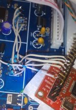
Hi Baka, let me clarify the i2s connection scheme according to the Nino's photo:
Brown : MCLK (Master Clock)
Red : BCLK (Bit Clock)
Orange : DATA (SDT)
Yellow : LRCK (FSCLK)
You should use ground plate of Dacs as i2s ground, not the AK4118's ground plate.
PS: I assume you are goin to disconnect the both four resistor group from receiver side and distribute each i2s pin to those legs, if you can't put AK4118 into PDN (powerdown) state with modified MCU.
Regards.
Attachments
Last edited:
Hi Baka, let me clarify the i2s connection scheme according to the Nino's photo:
Brown : MCLK (Master Clock)
Red : BCLK (Bit Clock)
Orange : DATA (SDT)
Yellow : LRCK (FSCLK)
You should use ground plate of Dacs as i2s ground, not the AK4118's ground plate.
Regards.
Thank you very much!
Will try as soon as possible.
Regards,
Goran
Thank you very much!
Will try as soon as possible.
Regards,
Goran
You're welcome. I edited the earlier post with an additional photo. You should isolate the resistors from AK4118 side, if you can't put AK4118 in PDN (as what Nino did using customized controller). I have also a customized controller but I haven't done required software modification yet.
Regards.
You're welcome. I edited the earlier post with an additional photo. You should isolate the resistors from AK4118 side, if you can't put AK4118 in PDN (as what Nino did using customized controller). I have also a customized controller but I haven't done required software modification yet.
Regards.
terranigma,
As I can see from the photo two channels share the same single signal?
For example: DATA wire (the orange one) ends to data resistors of both channels at the same time?
Regards,
terranigma,
As I can see from the photo two channels share the same single signal?
For example: DATA wire (the orange one) ends to data resistors of both channels at the same time?
Regards,
Yes, it is correct. You also can see it by following traces on pcb.
Regards.
Hi Baka, and thank you terranigma,
terranigma & I are using the Arduino controller. By doing so, we can initialize both DAC chips ourselves by software.
If I recall correctly, the original controller initializes both DACs to 24 bit I2S (mode 3) (the AK4113/AK4118 only does 16/24bit, datasheet page 30). In order to work with I2SoverUSB, DACs need to be setup for 32bit I2S instead (mode 7).
Regards, Nino
talking about i2s...
I'm wondering what you guys think about this. I'm currently designing some circuits for my project (this DAC with Arduino + I2SoverUSB + Odroid C1 into an old tuner enclosure4 using it's original LED display/controls), so I decided to design a small pcb to connect 1 i2s ribbon cable to the two DACs.
In the original design, the left DAC i2s lines are shorter than the right DAC's. From a clock-signal with delicate timing point of view, this is not ideal. I read an article about clock distribution with design tips. In this particular case, especially MCLK and LRCK are important, as the MCLK is used by delta-sigma modulator and LRCK is in fact 2*fs, so most closely related to fs.
It seemed simple to design the pcb, but it turned out to be a hell of a job, using the rules for sensitive clock signals. I ended up with the design shown in the attached picture. I2s resistors are removed and the board is soldered onto the holes at the dac side. Resistors on the board are 0805 SMT, bottom side of the board is entirely ground plane.
So, do you think this better design in theory would lead to better performance in reality? 🙁
Attachments
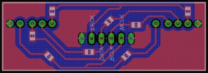
Hi Nino, for this particular purpose, we could attain same goal with wires at equal length and distributed from one place (which I did it by now). Your solution can make a obvious difference due to the ground plate and strictly routed vias.
Regards.
Regards.
Hi Baka, and thank you terranigma,
terranigma & I are using the Arduino controller. By doing so, we can initialize both DAC chips ourselves by software.
If I recall correctly, the original controller initializes both DACs to 24 bit I2S (mode 3) (the AK4113/AK4118 only does 16/24bit, datasheet page 30). In order to work with I2SoverUSB, DACs need to be setup for 32bit I2S instead (mode 7).
Regards, Nino
Hi Nino,
Sorry for my humble knowledge 🙁
Does that mean that just with the connection recommended by terranigma these DACs can or can not play 24 bit/96-192 files with I2SoverUSB or additional work is necessary anyway?
I would be perfectly fine with the above resolution...
Thanks,
Goran
Hi Goran
If you use the original controller, the AK4399 expects 24 bit i2s. No matter what format you want to play, data is sent using 24 bit. For 16 bit audio, least significant bits are zeros.
I'm using I2SoverUSB in combination with RPi and SqueezeLite. In this setup, all audio is output by the board using 32 bit i2s. I don't think this can be changed to 24 by software, perhaps you may ask JLSounds. [edit: see AK4399 datasheet page 19-21 for different interface modes]
So in my experience, in order to use I2SoverUSB, the DAC needs to be setup for 32 bit i2s instead of 24 bit, you have to replace the controller for that.
terranigma is using another board, Amanero, which probably outputs 24bit i2s.
Another problem is when you decide to use i2s only, sampling rate detection/display isn't working.
Last edited:
Thank you very much Nino.
I have noticed in the datasheet of the I2SoverUSB (page 2, table 2) that 24 bit output could be obtained by connecting the pin 1 and pin 4 with "R4 4.7kΩ
configuration resistance".
Could that be the solution for my needs?
If it is possible to achieve this I wouldn't care too much for the sampling rate detection and usage of the display.
I could then concentrate to further tweaking in order to make this DAC as better as possible.
Otherwise, I would give up this project at the very beginning...
Regards,
Goran
Thank you very much Nino.
...
Otherwise, I would give up this project at the very beginning...
Regards,
Goran
Seriously? 😉
The 24bit output of I2SoverUSB you're referring to is no i2s but Right Justified 24 bit, incompatible with i2s (see AK4399 datasheet).
As far as I can oversee this, the problem is that I2SoverUSB outputs BCLK in 128fs instead of 64fs. I think that's why mode 3 didn't work for me and I had to switch over to mode 7. If you want to know in depth, maybe you can ask JLSounds.
I used the board some time with sp/dif output, which was almost as good as the i2s I have now. I modified AK4113 before that, with a low noise reg on AVDD and corrected the TVDD voltage to 5V.
Of course you can also replace the controller with Arduino Nano, and have full control over settings.
Regards
Nino
Not being able to replace the DAC's microcontroller, i inserted an I2Sover USB board inside the chassis and connected it to the connector meant for Weiliang's own XMOS board, using I2SoverUSB's spdif output. The board is powered by two TPS supplies placed inside the chassis. I had changed TVDD voltage to 5V, that i believe is a simple and very good mod, plus some other mods (ground planes, regs, caps, etc...).
I better explain my I2SoverUSB mod previously in this thread, with some pics.
This setup sounds very good - a really BIG improvement upon Weiliang XMOS - and the mod is quite easy to do, as you don't have to bother with controllers or change the way AK4399s work.
I also tried connecting an isolated diyinhk XMOS board via I2S, it worked OK and sounded very good too; but, comparing to I2SoverUSB sdpif output, SQ was not better enough to justify the loss of other inputs (or the much higher complications).
Last edited:
Not being able to replace the DAC's microcontroller, i inserted an I2Sover USB board inside the chassis and connected it to the connector meant for Weiliang's own XMOS board, using I2SoverUSB's spdif output...
Hi Luca,
Would you please be so kind to post the way you made the connection between these two boards?
I have searched all your posts here but could not find a more specific info on how to do this.
Thank you and kind regards,
Goran
... maybe you can ask JLSounds...
Nino
Will contact them to see what they could do for me...
Thank you Nino.
- Status
- Not open for further replies.
- Home
- Source & Line
- Digital Line Level
- ebay:Weiliang Dual X2 AK4399 DAC with LCD