Have you read this one Êà÷åñòâî ÎÓ è Àïãðýéä ÑÄ ïðîèãðûâàòåëåé. Not only type of the input stage (FET/Bipolar) of op-amps is important. It is not new, but I understand why Lynx has selected those 3 op-amps for output stage / LPF.So - no surprise - this output stage needs a fast FET opamp.
Last edited:
Yup, I have. Thus my choice of ad744+811 for my ES9018 dac. Actually I'm slightly surprised by the fact that 49710 with rather low offset current sings like hell here. But it does, as does 49990 or 5534.
Hi pca01,
I used X7R 100n capacitors, 0402 size. The caps are for bypassing, so temperature stability/ accuracy is not that important, I see no reason to use NP0 ceramics of even smaller capacity (2.2n). 100n is also recommended in datasheet.
I used X7R 100n capacitors, 0402 size. The caps are for bypassing, so temperature stability/ accuracy is not that important, I see no reason to use NP0 ceramics of even smaller capacity (2.2n). 100n is also recommended in datasheet.
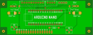
DAC Arduino PCB
I've received my PCBs and I would like to share the layout of PCB that I have already tested. At first, the Arduino MC PCB. The layout is in the SprintLayout 6.0 format. If it's needed, I can share the Gerber/Drill data files too.
This PCB may be used, for example, in the this case Aluminum DAC chassis enclosure for Soft control ES9018/AK4399 280*62*211.5mm | eBay
Attachments
Great, next step is atmega328 sans arduino? 🙂 Thanks for sharing.
I have received and replaced the AK4118, now it works. Keep trying to imagine when and how have I fried the first chip.
Btw, the sound is quite different from I2S from the XMOS module. When I incorporate both the receiver and the module, will tell you my impressions on direct comparison.
I have received and replaced the AK4118, now it works. Keep trying to imagine when and how have I fried the first chip.
Btw, the sound is quite different from I2S from the XMOS module. When I incorporate both the receiver and the module, will tell you my impressions on direct comparison.
pca01: Very nice! I wonder: I see a trace running from Anode pin of LCD, via 100R resistor, via 10 k potentiometer (good thing) to TX1 pin in the Nano. (?) Isn't that supposed to be running to +5V Vcc?
cu6apum: keep us posted, I'm experimenting with I2SoverUSB board too, via sp/dif atm, going to connect it with RPi running picoreplayer with linear psu
Nino
cu6apum: keep us posted, I'm experimenting with I2SoverUSB board too, via sp/dif atm, going to connect it with RPi running picoreplayer with linear psu
Nino
Well, a netplayer is my separate project. No usb (too weak on arm), i use direct i2s out of my cubietruck. Sounds nice at the mo with my Sabre board - but is quite far from finish yet.
Considering AK439x, you may want to use some neat reclock circuit close to DAC chips, as they're not as strong in jitter suppression as the 9018 is: it sings just fine with no reclock.
Considering AK439x, you may want to use some neat reclock circuit close to DAC chips, as they're not as strong in jitter suppression as the 9018 is: it sings just fine with no reclock.
Hi,
I use the TX1 to switch the LCD background light programmatically (when the MC is idle). This behavior is configurable via new menu screen. If this feature is not needed, it is possible to connect the 10K trimmer to the 5V source.
I use the TX1 to switch the LCD background light programmatically (when the MC is idle). This behavior is configurable via new menu screen. If this feature is not needed, it is possible to connect the 10K trimmer to the 5V source.
The BACKLIGHT (not contrast) consumes ~40mA, so it's not 10k, rather 120 ohm, and I doubt that any arduino pin can handle this. I'd use a mosfet switch.
Must be carefull with pin current, but 40mA is max dc current/pin for Arduino. Clever to shut down the backlight, and prettier🙂
Hi folks!
I faced with an annoying failure with my dual AK4399 DAC.
After a short disconnection of the LCD panel, I couldn't control it with the buttons. A few hours later the functions returned, however one of the input selector buttons remained useless. I ordered a new piece of microcontroller+LCD module from weiliang diyhifishop. As it arrived, I connected it, but same failure happened, I push any button in vain, nothing happens.
I put back the old module; result is just the same… starting to be upset now.
Anybody has any idea what to do?
I turned it off before any manipulation, of course.
Cables are tested, buttons are closing nicely the connections, too.
Cables are tested, buttons are closing nicely the connections, too.
I had a floating bug (see above) with flickering CS pin on my cable. Try bending and pulling it with your tester connected.
hi megaymir,
With the original controller only 2 of the 3 buttons are operational for this DAC. One for filter selection and the other for source selection. If I remember correctly, the 3rd button duplicates source selection.
With the original controller only 2 of the 3 buttons are operational for this DAC. One for filter selection and the other for source selection. If I remember correctly, the 3rd button duplicates source selection.
Last edited:
Initially all the three buttons functioned, two of them was to stepping the input up and down.
There is not a problem between the button pcb and the control module, because I tested the control module without the button pcb, just shorting the connections with my tweezer on the connector, without the cable plugged in.
By the time of first failure I tested all the connections with my tester but I'll do some investigation again. Maybe it's affordable to change all the connectors. I hope there is some stupid little failure.
I worked a lot on this DAC and I became more and more happy with the result.
Yes, it was a cable disruption. Thx for the input!
(The old control module still perceives two of the three buttons, the new one is fine, I can live with it.)
(The old control module still perceives two of the three buttons, the new one is fine, I can live with it.)
Hello
I have the V1.1 version of this board (blue pcb, AK4118 receiver). I am looking at doing the TVDD to 5v mod. It looks like this can be done by cutting one of the inductor coils and connecting a 5v supply there. Only problem is, my eyes aren't what they used to be and I can't follow the traces to see which one to tap into.
I know others have done this mod, and there used to be a photo showing which inductor to use, but it's no longer available. Has anyone still got it anywhere, or can anyone tell me which one to cut into?
Thanks in advance for any help!
- Status
- Not open for further replies.
- Home
- Source & Line
- Digital Line Level
- ebay:Weiliang Dual X2 AK4399 DAC with LCD