I would have been inclined to design my own pcb rather than try and fix the circuit/pcb mess they supply.
TheGimp,
According to the link/thread you mentioned, one of the calculations for SRPP, there were the following impedances:
Assuming bypassed lower cathode, Rk2=750, Ra=4400, mu=35 I get
Zout = 633 (full formula) or 541 (simple formula)
Zopt = 10925
So Output impedance was 633 Ohms or 541 Ohms,
But the optimum load impedance was 10,925 Ohms.
Yes, I admit that was for a different tube.
But I still think that any good 6SL7 SRPP output impedance is going to be much closer to 600 Ohms or 700 Ohms, than it is to 10k Ohms.
Just my opinion.
On my version there was a fairly low level of hum audible close to the speaker but could have been improved using one of the hum control methods discussed in threads on this site. With the re-make, the circuit included 5v regulation which works fine. Another who used the pcb. Though I didn’t have the volume issues cited. Cheap 300B project
Thanks for the tip.
I will re check my board and if I can't fix it yet (I am a beginner) I will try this other one.
I would have been inclined to design my own pcb rather than try and fix the circuit/pcb mess they supply.
The best solution but when you are a beginner it is not really possible.
Tubelab's TSE board....
You can always remain at the safe side and order Tubelab' s TSE board.
Tubelab SE Board | Tubelab
Plenty of info and tips.
George (Tubelab_com - diyaudio member) and others will be always so kind to help you.
Regards
You can always remain at the safe side and order Tubelab' s TSE board.
Tubelab SE Board | Tubelab
Plenty of info and tips.
George (Tubelab_com - diyaudio member) and others will be always so kind to help you.
Regards
I will check the hum pots then, for the moment they are set to half of the resistance of the pot as described in the assembly guide DOUK sent me.
Hum pots are meant to be used!, and are often very sensitive to adjust to the quietest position. Without an o'scope, listening will still work fine. Listen to one speaker at a time as you adjust, with your ear right next to the woofer.
Or, alternatively, connect headphones to each channel separately, both sides to the channel being adjusted. A handy homemade jig is a female 1/4" TRS jack with two flying clip leads, one to tip and ring and the other to sleeve.
All good fortune,
Chris
Ok, thanks you all for the advices, I guess I have a lot of work ahead. I have a pocket oscilloscope so I guess I am good to go.
And I will also check tubelab.
Great community 🙂
And I will also check tubelab.
Great community 🙂
George (TubeLab) makes really nice boards. I have several other designs of his.
I am trying to do a build with parts on hand (Iron & tubes). 5842s are still going for $20 ea, but are considerably higher on ebay. I don't have any so that would be an additional expense
I am trying to do a build with parts on hand (Iron & tubes). 5842s are still going for $20 ea, but are considerably higher on ebay. I don't have any so that would be an additional expense
Hum pots are meant to be used!, and are often very sensitive to adjust to the quietest position. Without an o'scope, listening will still work fine. Listen to one speaker at a time as you adjust, with your ear right next to the woofer.
Or, alternatively, connect headphones to each channel separately, both sides to the channel being adjusted. A handy homemade jig is a female 1/4" TRS jack with two flying clip leads, one to tip and ring and the other to sleeve.
All good fortune,
Chris
To set my hum pots, should I connect my speakers to keep everything under load and avoid to blow up my tubes?
To set my hum pots, should I connect my speakers to keep everything under load and avoid to blow up my tubes?
I would just adjust them listening to the speaker. If you adjust it to be at the quietest position at the speaker, isn't that what we are trying to do?
I would just adjust them listening to the speaker. If you adjust it to be at the quietest position at the speaker, isn't that what we are trying to do?
yes you are right 😀😀
Ebay tracking shows :
" Arrived at Regional Distribution Center
MONROE TOWNSHIP, NJ 08831"
It could be here early next week, depending on how it gets sorted and sent from NJ. I could drive there in about 8 hours.
" Arrived at Regional Distribution Center
MONROE TOWNSHIP, NJ 08831"
It could be here early next week, depending on how it gets sorted and sent from NJ. I could drive there in about 8 hours.
Well the kit finally arrived and I am tracing it out and making accurate documents for it before I start building.
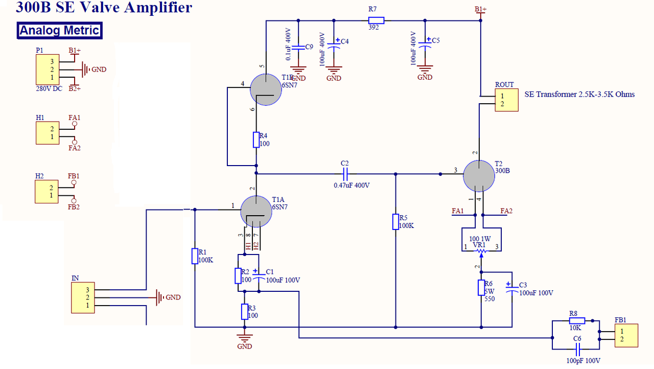
The schematic recommended for mods by Alashikata in post 4 is the closest match to what I believe I have.
so you don't have to go back, here it is again: DIY 300B Single-Ended-Triode (SET) Hi-Fi Amplifier Project
The schematic recommended for mods by Alashikata in post 4 is the closest match to what I believe I have.
so you don't have to go back, here it is again: DIY 300B Single-Ended-Triode (SET) Hi-Fi Amplifier Project
Actually you can mod anything you want. Just hold on to the resistors around 6SN7 where you can change around for mod.
Check out this schematic of pin 2, 4, 6 on 6SN7, it may be the one that match the pcb.
Check out this schematic of pin 2, 4, 6 on 6SN7, it may be the one that match the pcb.
For the schematic on Post # 56, there is only 550 Ohms for the 300B self bias resistor.
What is the B1+ voltage?
Be careful to not run so much current and so much B1+.
Current x Voltage = Plate dissipation.
Do not run the 300B too hot; and do not exceed the original 40 Watts maximum plate dissipation,
or more realistically 36 Watts (Western Electric later revised the 300B plate to 36 Watts maximum).
Happy building, happy adjusting, happy listening!
Last edited:
Good advice 6A3sUMMER.
I am thinking 320V for B+ with 70V for cathode bias for a Vak of 250V. Rather conservative, but it is based on transformers I have on hand. I will see if I can boost the B+.
Thanks Alashikata.
I believe that cathode bias resistor is 880R (R6) Plus P2/2 (100R/2) for a total of nearly 850R.. However I plan on over 1K for the cathode bias to keep the current conservative.
I plan to map out the schematic and post it.
I will then propose mods which I feel would benefit the design, and we can discuss.
I think I have a good schematic, but will wait until tomorrow to verify it before posting it.
At this point is appears to be a two stage 6SN7 common cathode gain stage direct coupled without any cathode bypass capacitors. This drives the 300B through a capacitor with bypassed cathode bias to the 300B.
I will have to calculate the gain of each stage without bypass to see if it has enough gain for my source.
Thanks all.
With a self bias resistor of 1k, and a bias voltage of 70V, that is 70mA of plate current.
49V self bias across 880 Ohms self bias resistor = 55.7mA plate current.
Do not forget the voltage drop of the plate current times the DCR of the output transformer primary.
Example:
DCR of 200 Ohms, and 50mA plate current = 10V drop from B+
Scroll down on this data sheet, and pick the operating points you want:
https://static1.squarespace.com/sta...45504889f6da688b7c8ecd/1598378059729/300B.pdf
Example:
300V plate to filament
-61V bias and 60mA = 1,017 Ohms self bias including the filalment balance pot Ohms/2
3400 Ohms output transformer primary.
5.6 Watts @
-30dB 2nd harmonic (3.16%)
-44dB 3rd harmonic (0.63%)
Plate dissipation 18 Watts
That would be 1.34% 2nd harmonic distortion at 1 Watt, and 0.11% 3rd harmonic distortion at 1 Watt.
That is a very good compromise of output power, distortion, and plate dissipation.
Just my opinions.
Last edited:
- Home
- Amplifiers
- Tubes / Valves
- eBay 300B PC board kit