Only czech is available, but translator is working quite well (translate it to english)
The drawing is lost 🙁
I appreciate your effort 🙂
The drawing is lost 🙁
I appreciate your effort 🙂
Miro, I have the same issues as I had befor turning the C2 by 180°. The Dac was recognized once by the Laptop, but not a second time. I added the 4 10R resistors and mounted the AD1862 and a pair of opamps and wanted to enjoy music, but it did not work. The dac was not recognized, neither by the computer, nor by the usb bridge :-(
Now I have run out of ideas. Any idea from your side? Cheers, Ernst
Now I have run out of ideas. Any idea from your side? Cheers, Ernst
@ernesternest Problem can be in a cold joint or a solder bridge in PCM2706 chip. Try to resolder all legs, be sure to use a flux.
EEVblog #186 - Soldering Tutorial Part 3 - Surface Mount - YouTube
If you fail to solve it up, you can send it to me by mail and I'll fix it and send it back to your address 🙂
EEVblog #186 - Soldering Tutorial Part 3 - Surface Mount - YouTube
If you fail to solve it up, you can send it to me by mail and I'll fix it and send it back to your address 🙂
more issues
Good morning,
I could solve the not being recognized issue, after I have mounted firstly another (used) pcm2706 and later another new one. Good! So I again checked all the voltages and then mounted 2 DACs and 2 opamps. The DACs are from ebay and do look good (the really good ones from Paddy I keep for the main DAC). And then I became really frustrated, as I got no sound out of the headamp :-(. So I connected the DAC to my HPA and heard just a very low volume and very distorted artefakt of sound. At least. Hm. Never faced so many issues in my long solder career.
Miro, any idea? I am going to check, if I forgot anything or have still anything soldered in a wrong way (hpa chip is soldered in the right way).
The story goes on.
Have a good day 🙂
@ernesternest
It's a quite complicated DAC, although simple in its form. I'm sure you'll find a solution.
Check all polarized capacitors.
Did you use 74HCT164D shift registers? (because there is also 74HC164D which is CMOS and thus not working with this DAC). Volume and distortion may be related to this.
The AD1862 from ebay should be fine, although I've seen cases where the leg in the case was broken and causing problems (only one channel, the second channel worked). Your case is probably related to both channels, focus attention to the shift registers. I am sure it will work 🙂
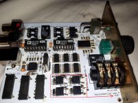
Miro, would you mind, sending a pic from the upper side?
The shift register is made from HCT. I used your bom numbers...
The shift register is made from HCT. I used your bom numbers...
Have you not one of the register soldered inverted ? The ones I have on the other dac have their printing difficult to see (pin1) without magnyfing glasses... check also the layout continuity with a buzzer...
If the pcm chip is seen by the PC with non muted volume, you will find it...
If the pcm chip is seen by the PC with non muted volume, you will find it...
Hi Iggy, yes, hope so. Meanwhile the 6120A2 works, but the output signal is like the cinch signal, just louder. I will go through the solderpoints and would appreciate a pic from Miro.
Hi Miro, thanks! I was not successful so far in getting anything better than before after checking all solders.
Mwybe I killed the the three 74HCT, wen I turned them? I could replace them....
Mwybe I killed the the three 74HCT, wen I turned them? I could replace them....
Hi @ernesternest, after checking the pins, 74HCT could be killed with incorrect rotation (GND with VCC is reversed). Do you have a digital analyzer to check digital data on the LRCK, BCK, DATA, DL and DR pins while the music/sine is ON?
Be sure to use single opamps (not dual version), like LM6171, or any other single type.
Be sure to use single opamps (not dual version), like LM6171, or any other single type.
Hi Miro, I don't have a digital analyzer. And the opamps are single ones. I think I still have a few 74HCT and I am going to exchange them vs new ones. Thanks
bad contact in the USB B board plug ?
recognized by the computer with the right device output ? No mute ?
Change of USB A port on the computer ?
recognized by the computer with the right device output ? No mute ?
Change of USB A port on the computer ?
Interesting issue ... a cheap logic digital usb analyzer from ebay could be handy, it cost 8USD.
Assume:
- all voltages are ok
- PCM2706 is recognized
- logic circuits 74HCT correctly installed
- opamps in I/V inserted/rotated correctly
- R9, R10 have the correct value (from 1k up to 2k5, default 1k4)
- DAC chips are in a working condition and installed correctly
Then there has to be nothing, why it shouldn't work.
Measure all SMD capacitors for a short circuit, check the capacity of tantalum capacitors (replace the one that was rotated incorrectly).
Send a few detailed photos if possible, to see component labels 🙂
btw, I already made the error with brown tantalum smd package, the thick black mark is the +... not like an electrolytic.
If the pcb board was printed ans sent raw free of parts, one may also assume to an print error... while they have AI looking at error when you send all the files ! Resist the temptation to try with the genuine Rochester chips...
leave your head from the pcb one week to do something else then re check it rested with a magnyfing glass and your voltmeter. You are certainly now too much focused to find imho.
Thank you both! I'll go through the list tomorrow. I should finish the AD1862 DAC in the meantime 🙂
- Home
- Source & Line
- Digital Line Level
- easyDAC = NOS R-2R AD1862 DAC + Headphone Amp