Looking at the shaft of the pot and the top of the board, 1, 2, 3 left to right.
opposite to how I thought then! OK I will try all these suggestions tomorrow and report back my findings.
Thanks, Mark.
I hope I soldered these jumpers on correct! I was unable to get any sound out of amplifier though.. I have +17.5v on all 4 op amps and -12v.
![URL]](/community/proxy.php?image=http%3A%2F%2F%5BURL%3Dhttp%3A%2F%2Fs5.photobucket.com%2Fuser%2F19mark70%2Fmedia%2Fcar%2520audio%2F20160515_091410_zpsdhzidier.jpg.html%5D%5BIMGDEAD%5Dhttps%3A%2F%2Fi5.photobucket.com%2Falbums%2Fy172%2F19mark70%2Fcar%2520audio%2F20160515_091410_zpsdhzidier.jpg%5B%2FIMGDEAD%5D%5B%2FURL%5D&hash=e02b22bf3e48840f2adb31ada3968ec5)
current draw dropped to 6.5amp with board in sink, I didn't want to take any chances with the power supply so clamped them down...
no vent on rail caps.
![URL]](/community/proxy.php?image=http%3A%2F%2F%5BURL%3Dhttp%3A%2F%2Fs5.photobucket.com%2Fuser%2F19mark70%2Fmedia%2Fcar%2520audio%2F20160515_091618_zps7lnktjcp.jpg.html%5D%5BIMGDEAD%5Dhttps%3A%2F%2Fi5.photobucket.com%2Falbums%2Fy172%2F19mark70%2Fcar%2520audio%2F20160515_091618_zps7lnktjcp.jpg%5B%2FIMGDEAD%5D%5B%2FURL%5D&hash=6acfe7cf94d835912bd5a874f8007575)
current draw dropped to 6.5amp with board in sink, I didn't want to take any chances with the power supply so clamped them down...
no vent on rail caps.
In each channel, measure the DC voltage from the emitter leg of one of the NPN output transistors to the leg of one of the PNP output transistors. Do you read more than about 0.001v DC in either channel?
In each channel, measure the DC voltage from the emitter leg of one of the NPN output transistors to the leg of one of the PNP output transistors. Do you read more than about 0.001v DC in either channel?
0.1mv accross the transistors and 1.6v on the actual ouputs (both)
I have ordered 6 new pots for the bass/treble/gain controls, I might as well change them all whilst I'm at it..
is there any other tests I can do to try and figure out what's wrong?
thanks for the help so far, much appreciated!
is there any other tests I can do to try and figure out what's wrong?
thanks for the help so far, much appreciated!
Reinstall the rectifier.
On the TL494, connect pin 16 to pin 7.
Insert a 10 amp fuse in the B+ line and power up the amp.
Does it power up?
Will it produce audio?
On the TL494, connect pin 16 to pin 7.
Insert a 10 amp fuse in the B+ line and power up the amp.
Does it power up?
Will it produce audio?
Been stated previously but to be clear... clamp all heatsink mounted components before applying power.
OK did all this, with the PWM jumped the amp turns on fine idles good.
there is some really terrible sound and on the outputs I'm measuring 32v DC on right channel and 8v DC on left.. all devices still ohming out OK at this point.
I pulled the treble pot that corresponds to this side of amp as well as it was damaged/loose so jumped 2/3 on those too.
there is some really terrible sound and on the outputs I'm measuring 32v DC on right channel and 8v DC on left.. all devices still ohming out OK at this point.
I pulled the treble pot that corresponds to this side of amp as well as it was damaged/loose so jumped 2/3 on those too.
Cut the treble pot jumpers (where you can reconnect them if necessary).
Does that change anything?
Are the positive and negative supply voltages to the op-amps equal now?
Does that change anything?
Are the positive and negative supply voltages to the op-amps equal now?
Cut the treble pot jumpers (where you can reconnect them if necessary).
Does that change anything?
Are the positive and negative supply voltages to the op-amps equal now?
no change in output, still lots of DC.
op amps have -29v and +16v
no audio until I turn headunit up from 0 to about 4 or 5 then lots of popping and distortion.
That's too much voltage on the op-amps. Measure the DC voltage directly across the terminals of ZD1 and ZD2.
That's too much voltage on the op-amps. Measure the DC voltage directly across the terminals of ZD1 and ZD2.
ZD1 = 15.6v
ZD2 = 15.6v
my new pots are on order and may arrive tomorrow or day after.
For many of the older autotek amps, the zeners are connected to secondary ground on one terminal and the other terminal is directly connected to the power supply pins of the op-amps. That doesn't seem to be the way this circuit works. What supplies voltage to the power supply pins of the op-amps?
I will have to remove board from sink to check that (times like this a schematic would be handy!). it's getting late here in UK now so will check tomorrow.
What supplies voltage to the power supply pins of the op-amps?
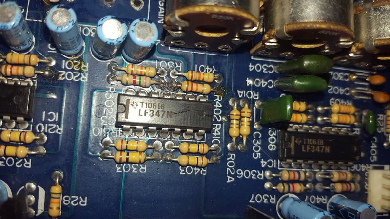
not quite sure where the ground comes from as it appears to go under the op amps and is a bit confusing without removing the op amps but the +V comes from the R218-R221 and then to the trnsistors to the left of them.

I thought that the rail voltage would go to the large resistors with the metal heatsinks, then to the zeners and from that node to the op-amp power supply pins. Is that wrong?
I thought that the rail voltage would go to the large resistors with the metal heatsinks, then to the zeners and from that node to the op-amp power supply pins. Is that wrong?
yes, you're correct, I wasn't following it that route! I have just fitted 6 new gain pots and also noticed lots of dry/bad soldering on the resistors around the op amps.. I will refresh these then refit
Last edited:
success!! one half of this amp is fixed and sounding very nice with a sense of lots of headroom! in the end I think it was a combination of those broken gain pots and really bad/dry solder as I re-soldered lots of bad looking solder. DC voltage is mv on outputs and everything checks out OK.
just one more question on this side of amp, the jumper wire on the PWM? is this safe to remove now and what was it's purpose?
many thanks, Mark.
just one more question on this side of amp, the jumper wire on the PWM? is this safe to remove now and what was it's purpose?
many thanks, Mark.
The jumper from 16 to 7 was to disable the protection circuit to allow you to troubleshoot. You can remove it.
- Status
- Not open for further replies.
- Home
- General Interest
- Car Audio
- Earthquake PA4300 help needed.