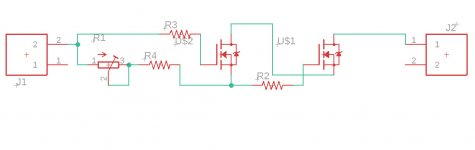
10M45? I assume you mean the switchable current regulator... It appears to me much like a TL431. But a bit more voltage beef. I think I can make a part for you
I see that 10M45 (to 252 pack) and DN2540 (to243AA) are made for smd.
Can you or anyone else makee those for me?
I am sure these footprints are available in Eagle, pretty standard.
What I do in cases like this, in the schematic, select any part that has the correct footprint and pinout, and later rename it to the part I want it to be. But then you have the 'link' to the footprint for the layout.
Not sure how that would work in Eagle but there should be a comparable method.
Jan
If you can holdup oh i dont know maybe a day I'll do the thing for you...however annoying it might be.
If you wonder how it's done the google "custom components in eagle" and there should be this quite old tutorial with eagle 5.6.X where this german guy shows you how it's done PROPERLY aswell. Btw it's on youtube.
If you wonder how it's done the google "custom components in eagle" and there should be this quite old tutorial with eagle 5.6.X where this german guy shows you how it's done PROPERLY aswell. Btw it's on youtube.
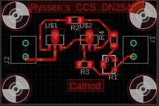
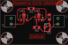
Edit:How do I edit the red text on the board seems like once it got there it is stuck there...
Attachments
Last edited:
Take a look at your selection filter!
Text can be moved, edited and so on, but filter has to be selected.
I can only ask you to show Autodesk EAGLE youtube videos with a lot of interesting stuff.
JP
Text can be moved, edited and so on, but filter has to be selected.
I can only ask you to show Autodesk EAGLE youtube videos with a lot of interesting stuff.
JP
What that means is that you have to tell Eagle what it is you want to edit or move etc. For that, the selection filter lets you select the item type you want to work on. You set it to parts, tracks or text (probably a few more options). So, select 'text' and then you can modify it.
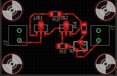
On the layout: delete that N$1, and re-route it nicely from the pad at J2.
R1: go from pin 2, to pin 3, then to R4. It doesn't change the electrical functionality, but the pictures in Stereophile look so much better ;-)
Jan
On the layout: delete that N$1, and re-route it nicely from the pad at J2.
R1: go from pin 2, to pin 3, then to R4. It doesn't change the electrical functionality, but the pictures in Stereophile look so much better ;-)
Jan
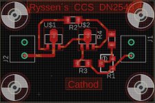
Starts to look rather nice. N$2 still looks a bit crooked. Can go up immediately from the pad at a 45deg angle.
Jan
Jan

Do you mean the components txt that is on the board?
I checked at JLC pcb´s site that I wont be on the finished board .
The white outline around pads.
Some of the outlines go onto pads which isn't good.
It can interfere with soldering.
- Home
- Design & Build
- Equipment & Tools
- Eagle question