This german engineer just could'n stand the pain of watching this anymore 😀.
He gave him the easy answer
He gave him the easy answer
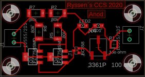
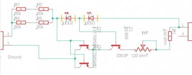
Never done enything in Eagle with smd before,thought I do a simple CCS for tubes.
But how do I found out the equalent to BC549C and MJE350?
Did a searh on google but found nothing
But how do I found out the equalent to BC549C and MJE350?
Did a searh on google but found nothing
Its actually fairly easy you find the closest SMD component with the same pinouts you need. OR alternatively use the
If youre using the lates eagle you will likely have a subcategory in the component library called as "DC_LOAD_AU" where youll find ALL transistor packages you could have dreamed of. Youll have to search for it manually you cant tipe it in the search bar and you have be concious about the packages..there maybe 3 different SOT23-3 packages with different CEB combinations on the pins. They all have it in their description and names and above all its displayed in the preview so they made it real difficult to mess up.
Good luck
Yes I´ve found the transistors,but when I trying to find the resistors I found that most of them can only take 200v so i will have to paralell or /and serill themm for both the voltage and the wattage...
Well my suggestion would be to use larger SMD resistors (2512 for 1W (with adequate ehat sinking mass in the soldering pads). Using SMDs for power stuff is kinda dumb except if you are trying to make a current shunt in wehich case 2010 is the go to cause you dont expect much power drop across it and its still not too too large
There are 1206 resistors that can take 600V (and MLCC capacitors aswell) or any other size. Just dont got with the trouble of paraleling and series connecting stuff. Do your homework good and proper so that you get the best results.
I personally like to combine SMD with THT because you can work arround not needing vias fairly easy. With the THT component solder points plated trough you can use it as a via but its nicely hidden and doesnt break the visual appeal...
Yeah I have OCD.
How sensitive is it when the trace go in between traces like a SND transsitor.
When using between 3-500v,do the soldermask isolate that?
When using between 3-500v,do the soldermask isolate that?
You route 500V tracks between smd transistor pads? 😱 😱 😱 😱How sensitive is it when the trace go in between traces like a SND transsitor.
When using between 3-500v,do the soldermask isolate that?
Ake,
why not starting with something much easier? You‘re starting with class D switching amplifier (I‘m finishing), now high voltage!
PS: green stop mask = 70V if I remember! But you‘ve to respect standards for creepage!
JP
why not starting with something much easier? You‘re starting with class D switching amplifier (I‘m finishing), now high voltage!
PS: green stop mask = 70V if I remember! But you‘ve to respect standards for creepage!
JP
You route 500V tracks between smd transistor pads? 😱 😱 😱 😱
No itt was the autorouter...🙄
You route 500V tracks between smd transistor pads? 😱 😱 😱 😱
Aint nobody have balls like this swedish guy. Swedish meatball it is.
If youre asking the dielectrical strenght of the soldermask well every manufacturer has their own charts or spec sheet. It heavily depends on the thickness of the soldermask and the material used...I know I kinda stated the obvious here.
I personally would not trust anything above 100V with soldermask. I mean obviously you have trouble walking with those hefty pieces of meat between your legs since you are daring to put a trace UNDER A SMD COMPONENT WHICH WILL BE ENERGISED AT 500V. Hell Id even go as far as routing the board. I did build a few HV stuff on PCBs but you need to think before do.
For the love of god do not use autorouter. As dave sais it NEVER TRUST THE AUTOROUTER. EEVblog #975 - Human vs Autorouter - YouTube (please do check this out, nice video and learn. I dont blame the autorouter...as they say the issue is between the steering wheel and the seat...essentially the driver. Just do it man. The autorouter is a pretty big procedure to set up in eagle DRC and it does not give any useable result whatsoever...lazy doesnt pay here. I have only used the autorouter for BGA and that also needed a human touchup soo yeah...NEVER TRUST THE AUTOROUTER. If you think thats how PCBs are done industrially well we would not need people like me or this very nice german guy who did the work for you on the ampliffier and didnt even ask for credit.
Also what in the gods mind have you come up that will do 500V ???????
10M45? I assume you mean the switchable current regulator... It appears to me much like a TL431. But a bit more voltage beef. I think I can make a part for you
Also what in the gods mind have you come up that will do 500V ???????
I`ll show you a little later...
No it was the autorouter...🙄
If you set the Design Rules for that particular net to keep a distance, it won't do that.
But I thought you were doing manual routing anyway?
Eagle autorouter really is just a toy.
Jan
It´s just this old one that have been floating around here for years.


But I couln´t find a transistor (smd) that takes more than 400v,so thats the limmit.
The text "Ground" on the schema is pin 2 at the connector..
Meat balls. hmmmm..
But I couln´t find a transistor (smd) that takes more than 400v,so thats the limmit.
The text "Ground" on the schema is pin 2 at the connector..
Meat balls. hmmmm..
Attachments
Probably worthwhile to look up Design Rule Checking, normally under DRC. This is a function where you can specify for the router (auto as well as manual) how much space to leave between tracks, between tracks and pads, between pads, etc.
I don't know how it is in Eagle but normally you can assign a 'type' to a track, like signal or power, and set the DRC for each type separately.
It is a great tool to automagically make sure that your PCB will be reliable.
Jan
I don't know how it is in Eagle but normally you can assign a 'type' to a track, like signal or power, and set the DRC for each type separately.
It is a great tool to automagically make sure that your PCB will be reliable.
Jan
- Home
- Design & Build
- Equipment & Tools
- Eagle question