Really? I can be shown easily that the balance of both output signals improves with increasing tail impedance. With a high impedance CCS tail you'll get well balanced signals even with dissimilar triodes.
Best regards!
Best regards!
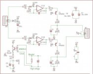
How about like this ?For the bias i was thinking of using the plug in modules ive made a PCB for to set the bias, see schematic and board attached, this will need a time delay to synchronize the application of B+ and bias to the tubes.
Mona
Attachments
v4lve lover,
Can it be I saw a quite similar auto bias system on zelfbouwaudio.nl? Do you have gerbers available for these boards? I made one with 4 opamps with a PCB I got from a user there. Works fine!
Regards, Gerrit
Can it be I saw a quite similar auto bias system on zelfbouwaudio.nl? Do you have gerbers available for these boards? I made one with 4 opamps with a PCB I got from a user there. Works fine!
Regards, Gerrit
Actually a LTP works fine even with a few kilo ohms resistor as a tail.
Really?....With a high impedance CCS tail you'll get well balanced signals even with dissimilar triodes.
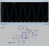
Attached is the normal LTP with a resistor at the tail. To get balanced output signals, the plate resistor of non inverting halve must be adjusted to higher resistance.
Usually fully balanced/equal signals from the phase inverter are not essential. It is essential that the level of output signals can be adjusted.
Output tubes may have a bit dissimilar gm and therefore to have balanced signals at the plates of the output tubes (which is essential) the drive signal of the output tubes should be adjusted individually.
The attached LTP produce required 40 Vpp drive with some 0.1...0.2 % THD.
Is that not OK ?
Attachments
Last edited:

Maybe. I prefer equal plate resistors, though, equal signal levels and don't really want to adjust.
Best regards!
Best regards!
I prefer equal plate resistors, though, equal signal levels and don't really want to adjust.
Why ?
By doing so the output stage generates even harmonics if output tubes are not completely matched which they not always be.
I would first adjust the DC-balance (bias) of output tubes and then AC-balance from phase inverter to minimum overall THD.
I would not be satisfied if I knew that the output of LTP is fully balanced, but the output stage is not.
Unequal plate resistors in LTP PI's resemble musical instruments amplifiers, which are FX devices and where it is ok, rather than HiFi ones.
Best regards!
Best regards!

It is better to use a simple current source , if you really want a tube one , and then the resistors can be equals .
But tor E130L , a pretty easy tube to drive , the cathodyne phase splitter is enough .
But tor E130L , a pretty easy tube to drive , the cathodyne phase splitter is enough .
Last edited:
It is better to use a simple current source , if you really want a tube one , and then the resistors can be equals .
Yes, to use CCS is clearly better. With CCS the THD is 0.1 % and with a resistor tail THD is 0.2% 😀
But the output stage generate 3...6% of THD😱.
I'm not worried , but using a CCS is allmost guaranteed to work right , you don't have to tweek resistors or add pots for equal output signals ...
using a CCS is allmost guaranteed to work right...
Yes, if you have fully matched output tubes, which usually happens only in theory.
But if you have not, then you need to adjust AC-balance, i.e. one of the plate resistors of the LTP to work right.
I have AC-balance adjustment in all of my designs and have noticed that it is useful if minimum overall THD is wanted.
How do you fine tune your amplifiers ? Just adjust bias ? Or something else too ?
Ordinary Cermet trimmers: Starelec Oy
I am not the only one who uses AC-balance adjustments. See last page of the attached document.
I am not the only one who uses AC-balance adjustments. See last page of the attached document.
Attachments
Last edited:
Yes, if you have fully matched output tubes, which usually happens only in theory.
But if you have not, then you need to adjust AC-balance, i.e. one of the plate resistors of the LTP to work right.
The CCS in the tail eliminates this concern. If the CCS is a good one, AC balance is strictly determined by resistor matching. Tube matching does not affect balance. You can visualize this in that current flow on an AC basis rocks back and forth between tubes, as it cannot change in the CCS.
The CCS in the tail eliminates this concern. If the CCS is a good one, AC balance is strictly determined by resistor matching.
It seems that you have not understood my point. We speak about different subject now.
My point is as follows: We have a push-pull output stage with typical unmatched tubes.
One tube requires, say 30 Vpp to be driven full and the other requires 35 Vpp.
If we now feed output tubes with 32.5 Vpp from "perfectly balanced" LTP, we are not at the optimum operating condition.
But if we instead "spoil" the perfect balance of the LTP and adjust it so that one output has 30 Vpp and the other 35 Vpp, then we have optimum operating condition.
- Home
- Amplifiers
- Tubes / Valves
- E130L PP Power Amplifier