Graaf -
The simple answer to the shape of the wavefront is that the "0" element (first driver) in a tapped delay line MUST be sent first, all others must lag. And then each one after must lag as well... so some shaping of the wavefront is possible, but the "string" that represents the wavefront has to fit between some point away from the plane of the speakers on one end back to the last element on the other. The time between discrete elements will cause the string to bend one way or the other, but any one point can be more than equal to either the element before or the element after...
As far as why the CBT is curved the way it is, I guess the best way to answer that is to read the paper and decide for yourself why he did this...
_-_-bear
PS. for your first drawing - it will look like the GREEN curve.
You can do the RED curve, but that requires feeding the "0" element from the center, not L & R from the outside...
Last edited:
PS. for your first drawing - it will look like the GREEN curve.
so my intuition was correct on this, however perhaps I couldn't express myself clearly enough
You can do the RED curve, but that requires feeding the "0" element from the center, not L & R from the outside...
but can we feed L & R from the outside to the same horizontal array as it seems that Jordan suggested? would the result look more or less like the green curve?
because Speaker Dave said it would not not work:
the thought that left and right are both fed to a common system and mixed signals radiate from some proportionate mid point. This notion is, of course, false.
or have I misunderstood Him? Can You please comment?
Good to see the ESL 63 mentioned. It is different than the Jordan drawing in that is an all-pass latice string. That is, each element gets a full range, essentially flat signal. The phase shift of each latice section comes from the LF path being straight across and the HF path criss-crossing for each element. The 180 degree phase flip causes some HF group delay.
The delay for each ring was enough to make the unit look like a sector of a large diameter sphere. Directivity was still pretty high but fairly constant and much less beamy than a conventional electrostatic.
Peter Walker once told me that it not only had delay for each ring but a little bit of level shifting of the outer rings that he thought was equivalent to the end flaring that Don Keele was using to improve his CD horns. It was all empirically derived.
I don't know if I have any in-depth info on the delay line he used. Can't remember why the inductors are drawn as transformers with shorted secondaries. I do remember they had a zillion turns of fine wire, which was okay since the electrostatic elements are fairly high impedance.
This points out the practical problem of a Jordan implementation: it is hard to get much effective delay with passive all-pass means. Walkers intention was HF delay to the outer rings of an electrostat. The Jordon requirement would be full range delay, at an amount high enough to give significant effective angling of a line, perhaps 10 feet wide.
I still maintain the end result is effectivly two cross firing line arrays. The fact that they are in one cabinet with a shared set of drivers doesn't really change anything.
David S.
Looks like the ESL 63 was discussed before.
http://www.diyaudio.com/forums/planars-exotics/46145-esl-63-what-type-coil-delay-line.html
Good article.
ESL63History
Peter's description of theory of operation.
http://www.quadesl.org/aes631.gif
http://www.quadesl.org/aes632.gif
http://www.quadesl.org/aes633.gif
David S.
http://www.diyaudio.com/forums/planars-exotics/46145-esl-63-what-type-coil-delay-line.html
Good article.
ESL63History
Peter's description of theory of operation.
http://www.quadesl.org/aes631.gif
http://www.quadesl.org/aes632.gif
http://www.quadesl.org/aes633.gif
David S.
Good to see the ESL 63 mentioned. It is different than the Jordan drawing in that is an all-pass latice string. That is, each element gets a full range, essentially flat signal.
perhaps that Jordan scheme was not the actual schematic but just for illustrative purposes? but anyway -
This points out the practical problem of a Jordan implementation: it is hard to get much effective delay with passive all-pass means. Walkers intention was HF delay to the outer rings of an electrostat. The Jordon requirement would be full range delay, at an amount high enough to give significant effective angling of a line, perhaps 10 feet wide.
but perhaps just some HF delay plus some level shifting plus some HF roll off would just do in the same sense as in ESL 63 it was sufficent to make it sound as a sector of a sphere?
perhaps full range angling of the line is not necessary?
another point - how much of delay is really required?
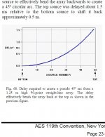
in CBT paper we can read that in case of a ground-plane CBT array of 125 cm it takes 1.5 ms of total delay between the driver at the bottom and the driver ot the top to make it sound like 45º circular arc (see the attached picture)
furthermore - paradoxically - imperfections of passive delay line could perhaps result in a kind of shading of the array (progressive towards the highs) - which is another thing that helps to achieve constant beamwidth
so -
I still maintain the end result is effectivly two cross firing line arrays. The fact that they are in one cabinet with a shared set of drivers doesn't really change anything.
- but perhaps Jordan's delay line array performed not just like two cross firing line arrays but more like two cross firing horizontally constant beamwidth line arrays?
which probably could be a good thing - at least it looks like that Dr Geddes suggestion points in this direction:
CBT is only constant beam height, the horizontal is not constant but falls just like any piston source. IMO they should be placed on their sides...
perhaps this is what Jordan's delay array could at least effectively approximate - two side-wall-plane horizontal constant beamwidth arrays?
in 2-in-1 loudspeaker hidden in a console-like piece of furniture?
how about that! isn't it impressive? in 1971!
can it be DIY-ed today?
Attachments
Last edited:
small dual-voice coil wide range perhaps?
L to one VC and R to the other?
for example:
TVM Acoustics, Valašské Meziøíèí - Hlubokotónové
not to big?
nice price, around 8 Euro here, would be <250 Euro for a 4 meter array
any alternatives?
L to one VC and R to the other?
for example:
An externally hosted image should be here but it was not working when we last tested it.
TVM Acoustics, Valašské Meziøíèí - Hlubokotónové
not to big?
nice price, around 8 Euro here, would be <250 Euro for a 4 meter array
any alternatives?
two more thoughts:
- realistically - a diy project could be aimed at the combined reflector-delay system - smaller and more convenient
- more audiophile way - perhaps LFs - say <160 Hz - could be summed to mono and fed into separate subwoofers? then perhaps it would be possible to use smaller wide ranges to achieve better HF and more continuous line?
subs could be OBs sitting in the corners - then the baffles could serve as reflectors as well
the setup could look like this:
Attachments

perhaps that Jordan scheme was not the actual schematic but just for illustrative purposes? but anyway -
A notional diagram, as I said in the beginning.
- but perhaps Jordan's delay line array performed not just like two cross firing line arrays but more like two cross firing horizontally constant beamwidth line arrays?
perhaps this is what Jordan's delay array could at least effectively approximate - two side-wall-plane horizontal constant beamwidth arrays?
Performed just like? To my knowledge it was never built. Hard to call it a constant beamwidth array when it was never really built. There is certainly no claim (or understanding at the time) that it was constant beamwidth.
Today we would call it "vaporware".
David
It's neat stuff though... and if built "properly" would appear to solve the issue of seat placement (left to right) once and for all! 😀
I would love to build a "pet" implementation of the idea some day... but I would not want to realize the delays in passive speaker level circuits... 😀
In other words, such a thing would not be low cost to say the least.
_-_-bear
I would love to build a "pet" implementation of the idea some day... but I would not want to realize the delays in passive speaker level circuits... 😀
In other words, such a thing would not be low cost to say the least.
_-_-bear
It's neat stuff though... and if built "properly" would appear to solve the issue of seat placement (left to right) once and for all! 😀
_-_-bear
Unfortunately not true.
Even though the left signal and right signal share all the same drivers the signals always eminate (first) from one end or the other. Feed a mono signal into both ends and sit off center and you will perceive two signals and the usual comb filtering.
I think people are thinking that a panpotted signal finds its proper location to radiate from somewhere along the length of the array. This is not true. It really is just a case of two sideways line arrays that happen to share drivers.
David S.
I also have this paper and about 20 years ago tried the reflector mentioned in it.
My attempt wasn't particularly sophisticated, using two fullrange drivers back-to-back and a couple of formica-topped panels as reflectors. It seemed to work OK. I was messing about with horn speakers at the time so didn't pursue it.
I haven't pursued the delay line but I did once ask Ted Jordan about it - he said that he thought his linear arrays (two vertical arrays of 4 units) had superseded the horizontal array.
I didn't ask any further details so don't know how it was achieved. Nowadays DSP would make it considerably easier.
Performed just like? To my knowledge it was never built. Hard to call it a constant beamwidth array when it was never really built.
...
Today we would call it "vaporware".
and Your knowledge is based upon...?
because in the 1971 article it is expressly written that the discussed setups were built and tested, we can read ia. that:
- about the sound of an express train rushing towards the listener standind at the end of the prototype full delay line[it] is frighteningly realistic
and
- about performance of the shortened delay line with side reflectorsit was wonderful for listening to grand opera
There is certainly no claim (or understanding at the time) that it was constant beamwidth.
can we conclude anything from the mere fact that modern terminology was not used?
Attachments
I haven't pursued the delay line but I did once ask Ted Jordan about it - he said that he thought his linear arrays (two vertical arrays of 4 units) had superseded the horizontal array.
as much more marketable for sure, it is significantly more difficult to sell a product that is too different from the competition 😉
the linear array is in fact a sort of cross-firing arrangement plus a bit more constant high frequency coverage plus on-wall placement
and Your knowledge is based upon...?
You implied that not only was it a miraculous solution but that it now had constant beamwidth attributes, a quality that Jordan never claimed.
My knowledge is based on 30 years of speaker design with a heavy concentration on network simulation. You can't string a bunch of drivers together with inductors in between and expect it to work as an effective delay line.
If you think you can, then show me measurements or a simulation (neither of which Jordan supplies).
Vaporware.
David S.
You implied that not only was it a miraculous solution but that it now had constant beamwidth attributes
oh really? Did I? where exactly?
do You understand the meaning of a phrase "it perhaps performed like" as opposed to "it was"?
My knowledge is based on 30 years of speaker design with a heavy concentration on network simulation.
...
Vaporware.
so Your knowledge that the device described as built and tested in the article was in fact never built nor tested is based on "30 years of speaker design with a heavy concentration on network simulation"?
so Your "30 years of speaker design with a heavy concentration on network simulation" gives You the right to discredit another engineer, quite renowned veteran as well, as a liar?
how so?
graaf,
best calm down. Speaker Dave is well qualified, he has explained where he comes from in other posts, iirc. You could ask him privately too.
regardless, I did not respond to what he said about the comb filtering effect for good reason. first, he might be correct, secondly I want to think about it some more before sticking my foot directly into my mouth...
It is important to understand that the best state-of-the-art in 1970 was not as sophisticated in an engineering sense as it is today. that was before computers of any power were available - even in large companies. The best sound coming out of a system in those days was perhaps on par with the best today, but the average was far far lower than today's "average". So, take what is written about the subjective impressions not quite on face value?
I think it is more important to gain insight into the pros and cons of designs, like this one, than to worry too much about the diplomatic skills of whomever is posting...
_-_-bear
If you believe the Jordan built a unit as described in the diagam (the inductor linked single array with left and right inputs) then I will let you explain two design problems that would be evident to a person with 30 years design experience. The first might be surmountable, the second isn't.
First, the diagram shows 20 units in the array. The low frequency impedance would be 1/20th of the drivers nominal impedance. With 16 ohm drivers we are talking 0.8 ohms. With either a tube amp or a transistor amp of that era, this would be a very difficult load. How do you think Jordan drove it? Even if we allow some DC resistance in the inductors, it will be below, say, 2 ohms for any inductor values that didn't cure the problem by defeating the purpose of the linkages.
Secondly, unfortunately the opposite channel amplifier is a short on the system. This is insurmountable.
For such a layout there are always 4 cases to consider: Same signal in both channels. Opposite signal (out of phase) in both channels. Signal to left channel only. Signal to right channel only. For three of those cases the output impedance of the opposite amplifier is a dead short to the line. That means for low frequencies (in fact for any frequency where the inductors are low Z) the line is shorted by the opposite amplifier. How does the speaker work when it is shorted? How does it radiate any low frequencies at all?
I know your enthusiasm for the unit to work as described is strong, but it can not. I don't know what Jordan built, but it wouldn't be the unit as drawn unless he had a magic solution to those first two problems.
Vaporware (vapourware?)
David S.
graaf,
best calm down.
I am calm, thank You 🙂
I think it is more important to gain insight into the pros and cons of designs, like this one
yes, absolutely
First, the diagram
should we really stick to this notional diagram (as You have rightly pointed out?)??
I don't know what Jordan built,
an honest answer, thank You
but it wouldn't be the unit as drawn unless he had a magic solution to those first two problems.
just for the sake of discussion - why magic? Jordan was manufacturing His own drivers since the beginning of His own business
He could make for example 64 Ohm VCs - combined 3.2 Ohm sound manageable? Even in 1971?
easily He could make dual VC drivers as well, why not?
good solutions?
Vaporware (vapourware?)
David S.
again - how can You? He expressly wrote that prototypes were up and running
And the fact that the line is shorted by the opposite amplifier?
Perhaps you should explain the theory of how it works since I've expressed the view that it can't.
David S.
Perhaps you should explain the theory of how it works since I've expressed the view that it can't.
David S.
- Status
- Not open for further replies.
- Home
- Loudspeakers
- Multi-Way
- E. J. Jordan Delay Line