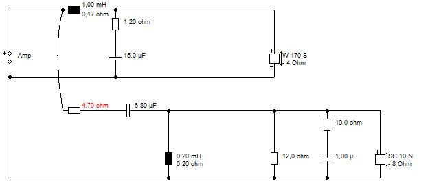
The crossover on the woofer is three components, it may result in a first order slope but it definitely isn't one component. It is closest to the one shown in #16, I've used that topology a few times. Inductor value should be in the 1-1.25mH range, you can read the rest of the values off Galu's image.
The rest of the components are for the tweeter, it doesn't look too complex. The 6.8 uF is the amplifier end, the 10 and 12 ohm are the L-pad. Which one goes where is determined by experimentation (usually the lower value is shunt). I would use a few values from 0.1 to 0.3mH for the little inductor. The 1uF cap is the 'air' cap. Usually placed in parallel with the series resistor in the L-pad.
The crossover is quite clearly a second order electrical type. The only way to get first order slopes out of that is by a very flat out-of-band (or rising) driver response.
hey guy, thanks for your assistance!
I'm highly experienced with building circuits, no worries 😉
Only that as you said, you came up with different component values and options. What would be closest to the original BM6 (passive) crossover?
I you give me a diagram and component values that would be the best fit, then I can build this easily 😉
But if the suggested design isn't close enough to true BM6 (passive), then maybe I should just go for a passive pair of monitors...
Arrange these components into a plausable Dynaudio crossover for the 17XL-4ohm bass and esowhatsit tweeter... 😕
Consults crystal ball... 😀
I get something different from Sangram. 4 ohm impedance at bottom end, but looks safe enough on very rough sim.
Attachments

Thanks a lot, so this last diagram should match the boards on the pictures, correct? seems easy to build!
Question:
You write: 0.2mH/0.2ohm , 1mH/0.17ohm
When I look for inductors online, I can only find their inductance value (mH) but no resistance (ohm). What am I missing?
Would you be able to link me to some of those?
Question:
You write: 0.2mH/0.2ohm , 1mH/0.17ohm
When I look for inductors online, I can only find their inductance value (mH) but no resistance (ohm). What am I missing?
Would you be able to link me to some of those?
Those are DCR numbers. You might not always find them on the product pages, but there should be a reference on the website. Copper prices keep fluctuating but the DCR usually doesn't so it reduces the number of updates:
Madisound Sidewinder Inductors 16 AWG: Madisound Speaker Components
18 AWG Air Core Inductor LW18 Series
Madisound Sidewinder Inductors 16 AWG: Madisound Speaker Components
18 AWG Air Core Inductor LW18 Series
Here are Dynaudio crossovers of a different model for a resonable price.
Do you think I could use these inductors and just replace the caps and resistors with the ones from the BM6 crossover?
Dynaudio Audience 122 crossover filter 2 pcs | eBay
Do you think I could use these inductors and just replace the caps and resistors with the ones from the BM6 crossover?
Dynaudio Audience 122 crossover filter 2 pcs | eBay
I'm not sure. The crossover looks quite different, likely designed to cross higher than a studio model. While you can get some sound out of it, it will probably not give you anything resembling a decent result.
A Ferrite Core bass coil tends to fairly low resistance without effort, because the ferrite increases inductance 4 fold, so half the wiring length need.
Air coils for tweeters are usually fairly low resistance, being small so again hover around 0.2-0.3R. Middle of the range coils tend to work well enough anyway. They are often specified by SWG wire.
It is easy enough to reduce the inductance of a coil, but increasing it could be awkward.
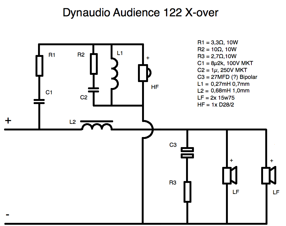
This is the schematic of the Dynaudio Audience 122, an MMT I believe:
Here's my idea for you:
Bit of work modifying that crossover on eBay. Wonder what shipping will cost?
Air coils for tweeters are usually fairly low resistance, being small so again hover around 0.2-0.3R. Middle of the range coils tend to work well enough anyway. They are often specified by SWG wire.
It is easy enough to reduce the inductance of a coil, but increasing it could be awkward.
This is the schematic of the Dynaudio Audience 122, an MMT I believe:
Here's my idea for you:
Bit of work modifying that crossover on eBay. Wonder what shipping will cost?
Until such times as you are confident about building your own crossovers you could get your project up and running with these inexpensive two-way crossovers from AliExpress: AIYIMA 2Pcs Bass Treble 2 Way Crossover Audio Board Fever Speaker Frequency Divider Crossover Filters For KASUN Home Theater|filter sticker|filter anthracitefilter foam - AliExpress
I ended up oredering this aliexpress crossover for now. Will report results when it arrives.
It's 3400Hz crossover point with 12db slope for both high and low channels, while the BM6P calls for 3100Hz with 6db slope for low, and 12db for high. Hope it's close enough.
So I received those crossovers from aliexpress. Results are ok, with my Quad 606 the BM6 sound way, way better than with their integrated amp, although with the integrated amp the low end is much more prominent.
I was wondering if there's an easy way to change the woofer slope from 12db to 6db as on the original BM6A.
Also if there's a way to change the cutoff from 3400KHz to 3100Khz?
I tried to draw schematics based on the PCB, hope this is correct...


I was wondering if there's an easy way to change the woofer slope from 12db to 6db as on the original BM6A.
Also if there's a way to change the cutoff from 3400KHz to 3100Khz?
I tried to draw schematics based on the PCB, hope this is correct...
As I stated earlier, the aliexpress crossover is simply a short term measure to get your project up and running.
The next step should be to concentrate on building a dedicated crossover as per Steve's post #27.
The next step should be to concentrate on building a dedicated crossover as per Steve's post #27.
Steve's images in post #27 are no longer appearing.
However, he had previously posted the circuit that I've attached. Perhaps he'll chip in again.
P.S. There's no way I can see of altering your aliexpress crossover to your specifications without changing out components - better to start from scratch with a dedicated design.
However, he had previously posted the circuit that I've attached. Perhaps he'll chip in again.
P.S. There's no way I can see of altering your aliexpress crossover to your specifications without changing out components - better to start from scratch with a dedicated design.
Attachments

I'd rather try to first modify that generic crossover and see how it sounds. Could you tell from the diagram what components need to be changed and to what values? for changing woofer slope to 6db? and the cutoff from 3400Khz to 3100Khz? thanks !
I'm afraid what you are asking for is tantamount to designing a crossover from scratch!
Do not agonise over the small difference in crossover frequency as it is not significant.
If you want to experiment (and it is only an experiment!) wth reducing the woofer slope, then try removing resistor R1 and capacitor C2.
Be prepared to re-insert the components if you don't like the result of removing them.
Last edited:
Sure. If you provide a set of frequency response and impedance of individual drivers in the box, I will be happy to help.Could you tell from the diagram what components need to be changed and to what values? for changing woofer slope to 6db? and the cutoff from 3400Khz to 3100Khz? thanks !
Measurements should be made on tweeter axis, speaker raised up off the floor, and 1m away. Off-axis would be nice to have too, but not mandatory.
Oh and I'll neeed inductor values as well, which you can get by puling the inductors and measuring them with a LCR meter.
There's also the option of waiting for someone who owns a passive set (I used to, but sold those a decade ago) and can pull a bunch of values for you from his set.

That's correct, without actually having to physically remove it, C1 will no longer be active in the circuit.
- Home
- Loudspeakers
- Multi-Way
- Dynaudio BM6 monitors crossover