I am trying to restore a Dynaco Mark IV and I just had the same bias filter capacitor explode twice.
When I found it, I first replaced the selenium rectifier with a 1n4007 diode, then did turn it on variac with all tubes except rectifier, tubes did turn on.
After, I turned it on with the rectifier. It did play music for few seconds, then I've noticed some smoke coming from a bias filter cap, so I turned it off.
I've checked the bias filter caps (there's two of them) with a capacitor meter. One tested within range (50~uf), the other one tested almost 0.
I've bought two new 50uf capacitors and replaced both.
Turned on the amp, with variac, first without rectifier, all tubes lit up.
Turned on the amp with rectifier. After few second, one of the two filter bias capacitor exploded.
Also, I was checking the voltage from the biaset pin. Just before the capacitor exploded, the bias voltage was quickly raising from 1v to above 2v.
Usually optimal bias should be set to 1.56v via the bias adjustment range.
What do you think it could be?
Thanks!
Hi,
Check the voltage across the capacitor and check if it is exceed the capacitor max voltage. Another thing that can cause the capacitor to exploded it is if you AC voltage. Check the diodes polarity to see if it is possible that you may have the polarity of the diode wrong.
Check the voltage across the capacitor and check if it is exceed the capacitor max voltage. Another thing that can cause the capacitor to exploded it is if you AC voltage. Check the diodes polarity to see if it is possible that you may have the polarity of the diode wrong.
Capacitor explosion can be due heat dissipation caused by 1) AC voltage is present 2) polarity reversed. The first explosion is understandable due AC present when the rectifier is shorted. The second is likely the new capacitor is reversed bias.
The fact that voltage on the cathode goes up due to bias is absence or 0.
The fact that voltage on the cathode goes up due to bias is absence or 0.
Last edited:
Check the voltage across the capacitor. Check the diodes polarity.
Yes, replace both of the bias caps and the diode, and use at least 100V rated bias caps.
Make sure that the positive terminals of the bias caps are grounded.
The diode's band is connected to the transformer lead because the bias voltage is negative.
You will get somewhat more negative grid bias voltage for the same pot setting with the silicon diode,
but that usually won't be a problem, just turn the pot up higher. Sometimes weaker output tubes
won't bias high enough with the silicon diode, unless you change the value of the bias supply resistor(s).
Last edited:
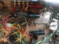
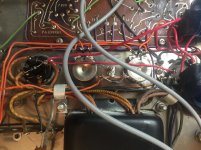
Here is a picture of how I wired the two capacitors and the diode.
Did I make a mistake on the diode polarity?
Attached is a diagram from the Dynaco manual. For that square box in the middle (selenium rectifier), negative polarity is toward the bias potentiometer.
So I did place the part with the gray line of the diode (is it negative, right?) toward the bias potentiometer.
Attachments
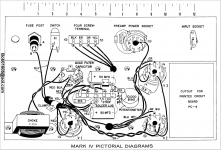
I did place the part with the gray line of the diode (is it negative, right?) toward the bias potentiometer.
Sounds like the diode was wired backwards. Make sure that the banded end of the diode
connects to the red/black transformer lead. Definitely replace both bias capacitors now also.
It's best not to think of the diode terminals as +/- but instead remember that current will flow
through the diode only if the banded end is at a more negative voltage than the unbanded end.
As a rule of thumb, if you want a positive DC voltage, take current from the banded diode end.
If you want a negative DC voltage, take current from the unbanded diode end, which is what
we want for the negative grid bias supply here.
Last edited:
It worked! Thanks guys for helping me troubleshooting it!
I replaced the diode and inverted its polarity. Replaced the exploded caps, works so far! 🙂
I replaced the diode and inverted its polarity. Replaced the exploded caps, works so far! 🙂
Hi,
Another thing that you must consider it is that when you replace a selenium rectifier with a silicon diode the final voltage would be higher. You may need to do some resistor values adjustment. I think your diode it is reverse. The band need to be connected to the transformer wire.
Another thing that you must consider it is that when you replace a selenium rectifier with a silicon diode the final voltage would be higher. You may need to do some resistor values adjustment. I think your diode it is reverse. The band need to be connected to the transformer wire.
I replaced the diode and inverted its polarity. Replaced the exploded caps, works so far! 🙂
Congrats, it should be fine now. The MklVs are great amps, better than the Stereo 70.
Later on you can restore it some more, after the bang recedes from memory.
Last edited:
I actually am restoring one Mark IV, two Mark III and one Stereo 70.
The Stereo 70 is the one in the worst condition. the Mark IV is pretty nice and the Mark III are very well kept.
This bring me to another question:
I have done the same selenium rectifier replacement on the Stereo 70. This time, I followed instructions from Bob Latino which found on another forum saying:
"The only minor thing that could happen is that in some amps after a change from the stock selenium rectifier to a diode the bias range will change somewhat. You won't get your "1.56 volts DC" bias voltage near the center of the bias control anymore. The standard thing to do if this does happen is to alter the values of the two 10K resistors on the 7 lug terminal strip. The usual cure is to add another 10K resistors in parallel with the 10K resistor between lugs 1 and 2 (to give a 5K effective resistance) and a larger 20K or so resistor in parallel with the 10K resistor that is now between lugs 3 and 4. A 20K resitor here will give you an effective 6.66K resistance between lugs 3 and 4. This should now give you the correct bias somewhere near the center of the bias control. The reason for the necessity of the resistor alterations is due to the greater forward flow of current by a diode as opposed to a selenium rectifier."
I have added this 10K and 20K resistor, but the bias voltage seem pretty high. With both the potentiometers on Stereo 70 to the extreme lowest, I reach 1.56v when I'm about 100v with the variac.
If I increase the voltage with the variac, or I move the potentiometers away from the minimum, I reach 2v to 4v on the bias pin.
Any idea of what could the problem be?
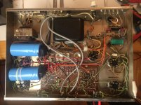
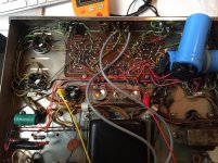
I am attaching a picture of the Stereo 70 with the replaced rectifier. I will also replace the two bias filter cap, which currently are 50uf, with some 100uf, which I will buy.
As last question, I found this Stereo 70 with two extra 100uf capacitors, which the previous owner connected somehow to the multi cap filter.
What is this practice for? What was he trying to achieve?
Thank you!!
The Stereo 70 is the one in the worst condition. the Mark IV is pretty nice and the Mark III are very well kept.
This bring me to another question:
I have done the same selenium rectifier replacement on the Stereo 70. This time, I followed instructions from Bob Latino which found on another forum saying:
"The only minor thing that could happen is that in some amps after a change from the stock selenium rectifier to a diode the bias range will change somewhat. You won't get your "1.56 volts DC" bias voltage near the center of the bias control anymore. The standard thing to do if this does happen is to alter the values of the two 10K resistors on the 7 lug terminal strip. The usual cure is to add another 10K resistors in parallel with the 10K resistor between lugs 1 and 2 (to give a 5K effective resistance) and a larger 20K or so resistor in parallel with the 10K resistor that is now between lugs 3 and 4. A 20K resitor here will give you an effective 6.66K resistance between lugs 3 and 4. This should now give you the correct bias somewhere near the center of the bias control. The reason for the necessity of the resistor alterations is due to the greater forward flow of current by a diode as opposed to a selenium rectifier."
I have added this 10K and 20K resistor, but the bias voltage seem pretty high. With both the potentiometers on Stereo 70 to the extreme lowest, I reach 1.56v when I'm about 100v with the variac.
If I increase the voltage with the variac, or I move the potentiometers away from the minimum, I reach 2v to 4v on the bias pin.
Any idea of what could the problem be?
I am attaching a picture of the Stereo 70 with the replaced rectifier. I will also replace the two bias filter cap, which currently are 50uf, with some 100uf, which I will buy.
As last question, I found this Stereo 70 with two extra 100uf capacitors, which the previous owner connected somehow to the multi cap filter.
What is this practice for? What was he trying to achieve?
Thank you!!
Attachments
Last edited:
I actually am restoring one Mark IV, two Mark III and one Stereo 70.
The Stereo 70 is the one in the worst condition. the Mark IV is pretty nice and the Mark III are very well kept.
This bring me to another question:
I have done the same selenium rectifier replacement on the Stereo 70. This time, I followed instructions from Bob Latino which found on another forum saying:
"The only minor thing that could happen is that in some amps after a change from the stock selenium rectifier to a diode the bias range will change somewhat. You won't get your "1.56 volts DC" bias voltage near the center of the bias control anymore. The standard thing to do if this does happen is to alter the values of the two 10K resistors on the 7 lug terminal strip. The usual cure is to add another 10K resistors in parallel with the 10K resistor between lugs 1 and 2 (to give a 5K effective resistance) and a larger 20K or so resistor in parallel with the 10K resistor that is now between lugs 3 and 4. A 20K resitor here will give you an effective 6.66K resistance between lugs 3 and 4. This should now give you the correct bias somewhere near the center of the bias control. The reason for the necessity of the resistor alterations is due to the greater forward flow of current by a diode as opposed to a selenium rectifier."
I have added this 10K and 20K resistor, but the bias voltage seem pretty high. With both the potentiometers on Stereo 70 to the extreme lowest, I reach 1.56v when I'm about 100v with the variac.
If I increase the voltage with the variac, or I move the potentiometers away from the minimum, I reach 2v to 4v on the bias pin.
Any idea of what could the problem be?
I am attaching a picture of the Stereo 70 with the replaced rectifier. I will also replace the two bias filter cap, which currently are 50uf, with some 100uf, which I will buy.
As last question, I found this Stereo 70 with two extra 100uf capacitors, which the previous owner connected somehow to the multi cap filter.
What is this practice for? What was he trying to achieve?
Thank you!!
Selenium rectifier has 1V drop compared to 0.7 to silicon diode, a difference of only 0.3V. so what is bias voltage at rectifier before and after change? If too great there is other difference beside the rectifier. If only minor increase in bias voltage, you only need to adjust resistor on ground side, just enough to makeup for the difference, not the rectifier side as the would increase bias some more.
The addition caps maybe for smoother ripple filters or hum reducer because original could be deteriorated already but not removed.
Last edited:
It's true that the forward drop is only slightly less, but the forwarding resistance is WAY smaller with a 1n4007 type diode. Thus a significantly higher voltage that might need adjusting the bias voltage divider.Selenium rectifier has 1V drop compared to 0.7 to silicon diode, a difference of only 0.3V. so what is bias voltage at rectifier before and after change? If too great there is other difference beside the rectifier. If only minor increase in bias voltage, you only need to adjust resistor on ground side, not the rectifier side as the would increase bias some more.
The addition caps maybe for smoother ripple filters or hum reducer because original could be deteriorated already but not removed.
It's true that the forward drop is only slightly less, but the forwarding resistance is WAY smaller with a 1n4007 type diode. Thus a significantly higher voltage that might need adjusting the bias voltage divider.
Oh ya, in addition it could be 2-3 stack, each stack drop 1V for about 70V bias supply, so actual drop is quite significant.
I have done the same selenium rectifier replacement on the Stereo 70.
If I increase the voltage with the variac, or I move the potentiometers
away from the minimum, I reach 2v to 4v on the bias pin.
I am attaching a picture of the Stereo 70 with the replaced rectifier.
I will also replace the two bias filter cap, which currently are 50uf,
with some 100uf, which I will buy.
I found this Stereo 70 with two extra 100uf capacitors, which the previous
owner connected somehow to the multi cap filter.What is this practice for?
Don't allow such high bias readings, since these reflect way too much current in the output tubes.
First try only a 10k in parallel with the resistor connected to the diode, and remove the other extra
resistor across the other 10k. Then you have: diode, 5k, and 10k to ground. This will give you more
negative voltage, to reduce the output current. Give that a try. We may have to readjust again
somewhat, but this should work.
Be careful not to turn up the Variac above 120V. Some Variacs can boost the mains
by 15%, up to 138V. That would probably do damage.
When replacing the bias caps, use at least 50uF each, but make sure that the voltage
rating is at least 100V.
The extra 100uF caps on the main filter supply do help filtering, but will strain the
rectifier tube. I'd remove the one connected directly to the rectifier tube, before
the choke. The one after the choke can stay.
I have tried removing both the 10k in parallel, but there is not much of a difference.
When my variac is at 90v, the negative voltage at the diode is -53.3v and the bias pin is 1.33v. If I increase the voltage at the variac, the bias voltage reaches 1.5v already at 100v, and this is with the bias potentiometer at minimum.
I've checked the voltage at various test points and compared it with the Dynaco original manual.
These measurement are done without any tube inserted in the amp, with variac at 115v
GZ-34 Rectifier
Pin 2 and 8: Manual 435v, multimeter 516v
Pin 4 and 6: Manual 360ac, multimeter 376ac
EL-34
Pin 2 connected to pin 7: Manual 6.4ac, multimeter 6.97ac
Pin 4 w ground: Manual 415v, multimeter 516v
Pin 5 or 6 w ground: Manual -32v, multimeter -42.3v
Selenium rectifier (Diode)
Bottom + lug: manual 50ac, multimeter 53.6ac
Top - lug: manual -65dc, multimeter 72.4dc
When I plug all tubes inside the amp, the rectifier negative dc is the following, with variac only at around 90v.
Top - lug: manual -65dc, multimeter -51.3dc
Is there anything weird in these voltages? What can I do?
1- when you say that the varic is at "90V" what AC is injected to the amp ? From the measurments given it seems to be much more then 110VAC
2- About the extra caps : remove them. Rebuild according to dynaco manual.
In my opinion : Any undocumented "improvement" is wrong and possibly harmful for your amp or the sound. It's certainly harmful for any future service.
2- About the extra caps : remove them. Rebuild according to dynaco manual.
In my opinion : Any undocumented "improvement" is wrong and possibly harmful for your amp or the sound. It's certainly harmful for any future service.
Hi,
Adding resistors in parallel will increase the voltage. What you need do it is add the resistor in series. This will increase the voltage drop across the resistor. Try adding the 10K resistor with 10K original resistor in series.
Adding resistors in parallel will increase the voltage. What you need do it is add the resistor in series. This will increase the voltage drop across the resistor. Try adding the 10K resistor with 10K original resistor in series.
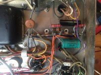
two diodes I found on the base of the rectifier tube.
Looks like the 2 added silicon diodes are in parallel with the tube rectifier sections,
so the B+ will be significantly higher than it should be. Try removing those 2 diodes
(just cut them off). Then the bias current will be less for a given negative grid bias.
This may not be all of your problem, though.
If one of the added B+ capacitors is in parallel with the first can capacitor section
(the one that is connected to the rectifier tube), you'll need to remove that capacitor,
because more than about 50uF there can stress the tube rectifier. In other words,
just go back to the stock Dyna circuit power supply.
- Status
- Not open for further replies.
- Home
- Amplifiers
- Tubes / Valves
- Dynaco Mark IV exploding bias filter capacitor