when you say that the varic is at "90V" what AC is injected to the amp ?
From the measurments given it seems to be much more then 110VAC.
It's possible for the Variac's dial reading to be lower than the actual output voltage,
depending on how it's wired. In fact, the Variac output can boost up to 15% over
the input voltage if it has been wired to do that. Measure the Variac output to be sure.
Last edited:
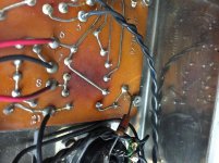
Looks like the 2 added silicon diodes are in parallel with the tube rectifier sections,
so the B+ will be significantly higher than it should be. Try removing those 2 diodes
(just cut them off). Then the bias current will be less for a given negative grid bias.
This may not be all of your problem, though.
If one of the added B+ capacitors is in parallel with the first can capacitor section
(the one that is connected to the rectifier tube), you'll need to remove that capacitor,
because more than about 50uF there can stress the tube rectifier. In other words,
just go back to the stock Dyna circuit power supply.
When I acquired this amp, it had all tubes except the rectifier tube.
May it be the previous owner modified this amp from tube rectified to diode rectified?
When I tested this amp and measured too high bias, I also used a rectifier tube. I wonder if trying it without rectifier tube the bias would then read within normal range.
When I acquired this amp, it had all tubes except the rectifier tube. May it be the
previous owner modified this amp from tube rectified to diode rectified? When
I tested this amp and measured too high bias, I also used a rectifier tube.
I wonder if trying it without rectifier tube the bias would then read within normal range.
The extra parallel HV diodes will "short out" the tube rectifier during operation, and the 5AR4
won't have any affect on the supply voltage, unless the silicon diodes are removed from the circuit.
If you delete the extra HV silicon diodes and caps, and insert the 5AR4, then it's back to stock.
None of the Dyna tube amps should be used with silicon diodes in the HV supply.
Last edited:
Good news! I've managed to fix again the Mark IV! One filter cap did explode again, and after investigating voltages I found out one EL34 was not getting negative voltage. The PCB input board had a crack in a corner (near eyelet 10) that interrupted one connection. I did flood some solder on it and now it works again. I tested the amp for an hour and so far so good.
I am using two RTF EL34 that test exactly the same on a Triplet 3414b. But when I test the negative pin 5 of each EL34, there is a difference between their negative voltage of 5~v. I guess that depends on the tube not being perfectly matched?
Meanwhile, the ST-70 is still on the bench. I've tried running it without tube rectifier, but still I do reach 1.4v bias pretty soon (when the variac is around 80-90v).
Attachments
PHP:
I am using two RTF EL34 that test exactly the same on a Triplet 3414b. But when I test
the negative pin 5 of each EL34, there is a difference between their negative voltage of 5~v.
The grid voltages of an EL34 pair should be the same, in the stock ST70. If your meter is not high impedance,
then directly measuring the grid (pin 5) will not give an accurate reading due to loading.
However, a leaky 0.1uF coupling capacitor can also cause a wrong grid voltage, and cause the tubes in a pair to differ.
The test for this is to disconnect one end of the suspect coupling capacitor, and remeasure the grid voltage.
Any change is due to leakage in that coupling capacitor, and it (or both) should be replaced.
Instead you could measure the DC voltage across the 270k grid resistors to look for excessive voltage drop,
if you have a high impedance meter. More than about 0.1VDC across the 270k indicates a problem, such as
a leaky coupling capacitor. In older amplifiers, 0.5VDC across the 270k due to coupling capacitor leakage
is not uncommon.
Last edited:
the ST-70 is still on the bench. I've tried running it without tube rectifier, but still I do reach
1.4v bias pretty soon (when the variac is around 80-90v).
If the HV silicon rectifier diodes are still in-circuit, they will bypass the 5AR4 when it is inserted in its socket.
Then the rectifier tube won't function normally, other than to draw filament current. The B+ will be too high,
and also not have a soft-start from the slow warm-up of the 5AR4.
Last edited:
PHP:
The grid voltages of an EL34 pair should be the same, in the stock ST70. If your meter is not high impedance,
then directly measuring the grid (pin 5) will not give an accurate reading due to loading.
However, a leaky 0.1uF coupling capacitor can also cause a wrong grid voltage, and cause the tubes in a pair to differ.
The test for this is to disconnect one end of the suspect coupling capacitor, and remeasure the grid voltage.
Any change is due to leakage in that coupling capacitor, and it (or both) should be replaced.
Instead you could measure the DC voltage across the 270k grid resistors to look for excessive voltage drop,
if you have a high impedance meter. More than about 0.1VDC across the 270k indicates a problem, such as
a leaky coupling capacitor. In older amplifiers, 0.5VDC across the 270k due to coupling capacitor leakage
is not uncommon.
Ops sorry, in this case I was referring to the Mark IV and not the ST-70.
I have tested a bunch of voltages and now they're all pretty close to what the manual states.
AC wall voltage: 123.3ac
Bias while playing music: 1.45v
Eyelets on preamp
11 -34.14
10 -33.4
9 -32.5
EL34 RTF V3 (in parentesis manual's voltages)
Pin 8 1.48 (1.56)
Pin 5 -32.4 (-34)
Pin 4 430 (432)
Pin 3 426 (432)
Pin 1 1.477 (1.56)
Pin 2 -- Pin 8 3.46ac (6.3ac)
EL34 RTF V4
Pin 8 1.48 (1.56)
Pin 5 -33.41 (-34)
Pin 4 431 (432)
Pin 3 427 (432)
Pin 1 1.48 (1.56)
Pin 2 -- Pin 8 3.45ac (6.3ac)
Philips 5gr4zy V1
Pin 1
Pin 2 439 (440)
Pin 3
Pin 4 400ac (370ac)
Pin 5
Pin 6 399.4ac (370ac)
Pin 7
Pin 8 439 (440)
Pin 9
Pin 2 -- Pin 8 5.48ac (5ac)
Quad Filter Capacitor
Lug 1 438
Lug 2 311.6
Lug 3 404.7
Lug 4 432v
The only value that seems out of range is Pin 2 with Pin 8 on each EL34. Manual says 6.3ac, but I read 3.45ac. What does could mean?
The only value that seems out of range is Pin 2 with Pin 8 on each EL34. Manual says 6.3ac, but I read 3.45ac. What does could mean?
The 6.3VAC is biased around zero volts so will give 3v either side on the heaters,
in this case I was referring to the Mark IV and not the ST-70.
Same circuit, just one channel in the chassis.
Just as update on the ST-70. I've removed the two silicon diode rectifier, removed the extra caps, used a normal rectifier tube and now all works well and I can bias the tubes 🙂
Thank you all
Thank you all
I've removed the two silicon diode rectifier, removed the extra caps, used a normal rectifier tube and now all works well and I can bias the tubes 🙂
That lowers the B+ by around 40V, back to normal.
- Status
- Not open for further replies.
- Home
- Amplifiers
- Tubes / Valves
- Dynaco Mark IV exploding bias filter capacitor