Dx Precision 1, a working prototype
Hello Sir Carlos,
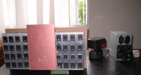
I had made another prototype of Dx P1 and this time it is working properly, as a lesson to learn when building the P1, this time i had measure the resistance of all the resistors before i solder in the board and check all the transistors for PNP/NPN type and i find some are not working properly, the resistors some times more sometimes less on there respective value and i have to reject some of them, next time i will use metal film for better accuracy, now i have an offset of around 5.2milivolts, as seen in the pictures i attached. And another thing is i read the whole thread of the P1 forum because there are some changes in the schematics and values of the resistors used and finally i find out the initial setting of the VR1(500R) is 330 ohms, and when i made the initial testing with the amp it is working properly. Nice sound, deep bass punch, clear treble, and very quite on stand by its like the amp is switch off. I only notice one thing, R16 10k 3watts resistor reaches a temperature of 61 degrees, and R6 3.9k 3watts resistor reaches 45 degrees, is it normal? or i have to increase the wattage of the resistors? I got this measurements when using the amp on a 1/3 volume on the amp, using a 10K potentiometer, connected to my computer. Please advice me Sir Carlos.
Regards,
Marjohn


Hello Sir Carlos,
I had made another prototype of Dx P1 and this time it is working properly, as a lesson to learn when building the P1, this time i had measure the resistance of all the resistors before i solder in the board and check all the transistors for PNP/NPN type and i find some are not working properly, the resistors some times more sometimes less on there respective value and i have to reject some of them, next time i will use metal film for better accuracy, now i have an offset of around 5.2milivolts, as seen in the pictures i attached. And another thing is i read the whole thread of the P1 forum because there are some changes in the schematics and values of the resistors used and finally i find out the initial setting of the VR1(500R) is 330 ohms, and when i made the initial testing with the amp it is working properly. Nice sound, deep bass punch, clear treble, and very quite on stand by its like the amp is switch off. I only notice one thing, R16 10k 3watts resistor reaches a temperature of 61 degrees, and R6 3.9k 3watts resistor reaches 45 degrees, is it normal? or i have to increase the wattage of the resistors? I got this measurements when using the amp on a 1/3 volume on the amp, using a 10K potentiometer, connected to my computer. Please advice me Sir Carlos.
Regards,
Marjohn
Last edited:
This resistance is too much hot...it is better to increase the watts ratio
Thank you by your pictures.
These resistances should be 10 degrees celsius above your environment temperature..or i made a mistake in the calculation or your resistances are not that real wattage.
regards,
Carlos
Thank you by your pictures.
These resistances should be 10 degrees celsius above your environment temperature..or i made a mistake in the calculation or your resistances are not that real wattage.
regards,
Carlos
Last edited:
I am building this amplifier. It is my first time making PCBs as well. I am getting the hang of it. Just toner transfer iron-on method.
I now have all of the parts, and the other circuits besides the dx precision are just about done.
All of the parts:
200 OK
Nearly every part will be used in this, which is my first big project. I will use mostly precision 1% resistors for the DX Precision. Any capacitors directly in signal path are either poly film or nichicon muse.
Summing op amp circuit to provide my powered subwoofer:
200 OK
As you can see, this one's top layer did not turn out great.
Circuit to drive my Peak Power Meters:
200 OK
The IC is a TA7318, scavenged along with the PPMs, and the transformer I am using from an old Denon Amplifier. Circuit was designed mostly by datasheet, with some mods to application circuit based on certain component values used in the denon schematic. Check out this transformer and the meters:
200 OK
I have the gerber files that destroy x has posted, and found a website online that has converted them to .png
Here are my .png files for the pcb:
http://dl.dropbox.com/u/5430178/converted dx gerb/Images for botmask.bms/botmask.bms.png
http://dl.dropbox.com/u/5430178/converted dx gerb/Images for bottom.bot/bottom.bot.png
http://dl.dropbox.com/u/5430178/converted dx gerb/botsilk.bsl.png
http://dl.dropbox.com/u/5430178/converted dx gerb/topmask.msk.png
http://dl.dropbox.com/u/5430178/converted dx gerb/topsilk.slk.png
Would somebody be willing to glance over them and check if they are correct? And I have an important question as well. When printing from Eagle for pcb, you print the bottom layer normal, and the top layer mirrored, this way the pcb is as it should when it is made. Do I do the same with these files for the dx amp? Thank you.
I will post pictures of newly completed circuits as I complete them.
EDIT: regarding my quesiton above, it may be an extremely stupid question, given the fact that the text on the bottom layer is reversed, so when applied to pcb it would be normal. The text for the top silk layer is normal, so I would have to print it reversed. Still, a confirmation of this would be appreciated.
Last edited:
Well, first channel pcb is in the cupric chloride solution.
http://dl.dropbox.com/u/5430178/project pics/dx channel 1 b4 etch.jpg
Hard to see some traces in the pic, but they are all good.
http://dl.dropbox.com/u/5430178/project pics/dx channel 1 b4 etch.jpg
Hard to see some traces in the pic, but they are all good.
Last edited:
Nice..... very nice...i am working in something even stronger
The MAKO.... i am preparing a less ugly prototype because i have not courage folks running unit, the prototype assembled...i will produce a less ugly one in a week or less.
I hope you will apreciate the Precision 1 .... nice amplifier....i believe you gonna enjoy it.
Thank you for sharing picture.
I do not remember details about it..because a long time was passed since Precision I was released...but needing anything, then go to:
nanabrother@hotmail.com
Or post here, but i may delay to answer as i'm having a very reduced internet activity due the fact i am running several projects at same time.
regards,
Carlos
Attachments

Last edited:
The MAKO.... i am preparing a less ugly prototype because i have not courage folks running unit, the prototype assembled...i will produce a less ugly one in a week or less.
I hope you will apreciate the Precision 1 .... nice amplifier....i believe you gonna enjoy it.
Thank you for sharing picture.
I do not remember details about it..because a long time was passed since Precision I was released...but needing anything, then go to:
nanabrother@hotmail.com
Or post here, but i may delay to answer as i'm having a very reduced internet activity due the fact i am running several projects at same time.
regards,
Carlos
Thank you. I am excited to get it done. I realize now, though, that I should have etched this:
http://www.diyaudio.com/forums/soli...ebugged-better-than-hrii-141.html#post1908566
Instead of the gerber files posted here:
http://www.diyaudio.com/forums/soli...ebugged-better-than-hrii-143.html#post2563510
Am I right? So far the only differences I can see are with ground connections. Should I be worried?
I cannot remember....gimme some time and i will check both options
There's a stone inside my left kidney bothering me a lot.... as soon as a heal i will check that.
I am busy and a little bit sick.
regards,
Carlos
There's a stone inside my left kidney bothering me a lot.... as soon as a heal i will check that.
I am busy and a little bit sick.
regards,
Carlos
Last edited:
There's a stone inside my left kidney bothering me a lot.... as soon as a heal i will check that.
I am busy and a little bit sick.
regards,
Carlos
Carlos, take your time, no worries. Hope you get well quickly. I am going to build it as is. I used the gerber files so its not as if it is not going to work. I just think there was a revision either before or after the gerber files, and that is why the slight difference. The differences are really small. All electrical connections are still the same, as well as component values.
Thanks,
Aaron.
Thank you by your understanding
I hope the thread has all you need to realise solutions for some small doubts.
regards,
Carlos
I hope the thread has all you need to realise solutions for some small doubts.
regards,
Carlos
Just a heads up to anybody wanting to build this. The gerber files posted a page or two back are of version 8. I found this out on page 74. The last, final version is version 8.1, and from reading, the difference is the grounding. Nothing else. I haven't found the gerbers for the last version, yet. This thread is huge. Gigantic. It is very hard to go through every post.
Please tell me that the V8 PCB is OK. Etching that PCB was quite hard with it being first time really making PCBs, and drilling all those holes with incorrect equipment. I hope I don't have to do it all over again.
Anyway, remaining optimistic, here is a pic of the pretty-much completed channel:
200 OK
My favorite part!
200 OK
200 OK
I have a bad trimpot in there for bias. One mm one way, and I get 5-6mv across the emitter resistors. One mm the other way, and I get 200mv. Resistance check shows the resistance jumps at that point. Damn. Got to run all the way home on lunch break to get another (hopefully good) one. Yep, I do this at work. Shhhhh! Don't tell anybody.
Initial test, when I had 5-6mv bias, with an utterly crappy test speaker, using my cell phone as a source, revealed a very nice sound. Further comment when this is sorted out. You like the blanket?
200 OK
200 OK
I have a bad trimpot in there for bias. One mm one way, and I get 5-6mv across the emitter resistors. One mm the other way, and I get 200mv. Resistance check shows the resistance jumps at that point. Damn. Got to run all the way home on lunch break to get another (hopefully good) one. Yep, I do this at work. Shhhhh! Don't tell anybody.
Initial test, when I had 5-6mv bias, with an utterly crappy test speaker, using my cell phone as a source, revealed a very nice sound. Further comment when this is sorted out. You like the blanket?
scratch that last comment. The pot is not defective. I replaced it with a good one, only to have it still do the same thing. Re-testing of each pot reveals they are both OK. Upon further testing, the resistance of the pot does not have an effect on the symptom. The amp intermittently is unstable. I will plug it in and operate it fine for a while, then it will jump to hundred mA or more, dance around for a bit, then I unplug it. Plug it back in, it is fine. Plug it in a third time, unstable. Odd. When this happens, the heatsink will warm up a bit, but not hot. When this doesn't happen, the heatsink is dead cold. The amp still plays audio fine while this is happening as well. No odd noises either. I have checked and re-checked for cold solder connections, but I will re-check again.
For testing, on the heatsink, the PNP output transistors are not isolated, but the NPN's are. Could this have anything to do with it? I will find out sooner or later when I put them on the heatsinks where they will stay, which means drilling, isolating with pads and making sure each transistor is completely electrically isolated.
For testing, on the heatsink, the PNP output transistors are not isolated, but the NPN's are. Could this have anything to do with it? I will find out sooner or later when I put them on the heatsinks where they will stay, which means drilling, isolating with pads and making sure each transistor is completely electrically isolated.
Last edited:
I've seen that happen with fake output transistors before... the ones we use are very prone to being fake.
I've seen that happen with fake output transistors before... the ones we use are very prone to being fake.
These are what I ordered:
2SA1943OTU Fairchild Semiconductor Digital Transistors / Resistor Biased
2SC5200OTU Fairchild Semiconductor Bipolar Power
I will try to look at them later and see if i can compare with some known good pictures on the internet or something. Any other possibilities?
Thank You
Go ahead and disregard the last few posts. I found an intermittently broken trace. That's what you get when you're a newb at making pcbs. Well, this is good: I learned something.
After repairing the trace, I spent several hours listening at various volume levels into a 4 ohm load.
The amp sounds wonderful! I have less than 1mv of offset. Yep, less than 0.001 volts. No noise that I can hear, even with ear against speaker! When carlos spoke of the drums and percussion through this amp he was not lying. They are wonderful. They will smack you in your face beautifully. I found the treble just as well. I am hearing nuances in my songs that I haven't heard, and this is in mono, only one channel done so far. This is also with a crappy test speaker. I am now etching the second board. I also have some higher quality parts that I've decided to use. I am going to use Nichicon MUSE for every electrolytic cap in these amps. When it is completed, There will be a tiny 60mm silent fan running at half speed for exhaust. The heatsinks stayed cool even at high levels, but the fan will give me more reassurance. This is will 3.5mv across each emitter resistor. Right now, they are lower quality wire-wound resistors, but when I can, I will replace them with metal film types.
Thank you Odysseybmx414.
Nice review...thank you are you told that i told the truth....yep...i use to do this way.
regards,
Carlos
Nice review...thank you are you told that i told the truth....yep...i use to do this way.
regards,
Carlos
- Status
- Not open for further replies.
- Home
- Amplifiers
- Solid State
- Dx Precision, finally released... now debugged and better than HRII