The reasons of this peak
Hey Murry, I have to ask if you are joking about a 0.003% peak?
Thanks for simulating the Precision and reporting on it. Glad to know its simulated performance is independently verified.
Cheers,
Francois
Muz said:Hi Carlos,
It's good from 300Hz - 20kHz (under 0.003%), but there's a peak of 0.03% at around 40Hz.
Murray
Hey Murry, I have to ask if you are joking about a 0.003% peak?
Thanks for simulating the Precision and reporting on it. Glad to know its simulated performance is independently verified.
Cheers,
Francois
Re: The reasons of this peak
Hi Francois,
First, I must say that I'm simulating using the very last final schematic circuit values, but I'm using OnSemi MJL4302 and MJL4281 output device models instead of the 2SC5200/2SA1943 pairs. (Because I have heaps of the MJL's in my parts box.)
Have a look at the THD plot in my previous post.
There is a 0.03% peak in the THD plot at 40Hz that is caused by the GFB falling off at these frequencies. The THD then falls to a low of 0.0002% at around 1kHz and slowly rises to 0.0027% at 20kHz. This is a very good THD result, and I don't think the rise in THD at the lower frequencies will matter very much, because most of us can't hear that low, let alone hear those levels of distortion. Besides, some of the best amps I've listened to have had THD = 0.04% across the spectrum.
But I can't help but wonder whether pushing that THD peak down a bit lower in frequency would be a good idea or not. Changing C7 to 1000uF would do the trick. Carlos originally had C7 at 1000uF but changed it to 470uF in the last schematic - I'm not sure why, though.
Cheers,
Murray
Francois G said:
Hey Murry, I have to ask if you are joking about a 0.003% peak?
Thanks for simulating the Precision and reporting on it. Glad to know its simulated performance is independently verified.
Cheers,
Francois
Hi Francois,
First, I must say that I'm simulating using the very last final schematic circuit values, but I'm using OnSemi MJL4302 and MJL4281 output device models instead of the 2SC5200/2SA1943 pairs. (Because I have heaps of the MJL's in my parts box.)
Have a look at the THD plot in my previous post.
There is a 0.03% peak in the THD plot at 40Hz that is caused by the GFB falling off at these frequencies. The THD then falls to a low of 0.0002% at around 1kHz and slowly rises to 0.0027% at 20kHz. This is a very good THD result, and I don't think the rise in THD at the lower frequencies will matter very much, because most of us can't hear that low, let alone hear those levels of distortion. Besides, some of the best amps I've listened to have had THD = 0.04% across the spectrum.
But I can't help but wonder whether pushing that THD peak down a bit lower in frequency would be a good idea or not. Changing C7 to 1000uF would do the trick. Carlos originally had C7 at 1000uF but changed it to 470uF in the last schematic - I'm not sure why, though.
Cheers,
Murray
Murray,
If the distortion at 40Hz is primarily H2/H3, then it clearly contributes to the 'huge' bass Carlos has described, and maybe it should be left as it is?
Most people like a powerful bass; if it's H2 with a little sharpening with H3 then all the better....
The very good distortion performance at 20KHz is unusual and points to the exceptional accuracy of the error correction due to the CFP input stage.
Hugh
AKSA said:Murray,
If the distortion at 40Hz is primarily H2/H3, then it clearly contributes to the 'huge' bass Carlos has described, and maybe it should be left as it is?
Most people like a powerful bass; if it's H2 with a little sharpening with H3 then all the better....
The very good distortion performance at 20KHz is unusual and points to the exceptional accuracy of the error correction due to the CFP input stage.
Hugh
Hi Hugh,
I was hoping you'd weigh in on the conversation 🙂 . Yes - the distortion is primarily 2nd harmonic with the 3rd a further 3dB down. And what you say makes sense.
Thanks,
Murray
Input topologie was because off Hugh...he said this circuit sounds fine
And i use to listen what he says, as 99 from a 100 things he says are always correct.
I have checked that Doctor Self have published the topologie and i have decided to use it, to listen to it and i found excelent the results.... it is not my discovery.... was Doctor Self i think, also Hugh Dean and Giaime that have used into his amplifier (My Amp).
The condenser choice, a reduction to 470uf, was a try to reduce the diameter, reduce the size as people loves to use high voltage units there and this turns the unit very big in size... also i had the need to avoid diodes to limit the voltage as i have some fear related diodes into the circuit, as a consequence of some bad experiences i had using diodes when i was building Linear Amplifiers to Radio Amateurs, several years ago.
I have tried 1000uf but could not have audible differences, so i have decided to reduce the value with the main focus to reduce the unit's size... but i had some advantage while i was trying 2 units, 1000uf each one, connected opposite one to the other, i could feel some small difference i could not conclude if better or worse, so small it was.
Thank you by the measurements made.
regards,
Carlos
.........................................................................................................
Collin Brown, Vinyl addict
I remember about the schematic you have asked.... it is not ready dear Collin, we are focused in model one and i am not even sure if the model 2 will be really released.
I think i have sent you the previous model 2 model.
As soon as i have assembled once more and adjusted i will send you informations and schematics as we made agreement about that..... i remember, of course!
Also Hugh Dean has my schematic too, i use to listen his ideas about.
the best regards to you.
Carlos
Hi guys, Ok, for the rebuild, I managed to shift most of the resistors over to 10mm pitch...
First rule of PCB fightclub, never say never!
The footprint for the cap you are discussing will handle 1000uf easily, especialy as it can even be a 16V unit to the best of my knowledge...
First rule of PCB fightclub, never say never!
The footprint for the cap you are discussing will handle 1000uf easily, especialy as it can even be a 16V unit to the best of my knowledge...
Well boys... a big surprise to me that Precision One (Roman letter "I")
Is measuring so well...or, better than reasonable.
I have tested using my simulator, but he is always trying to "polish my shoes" and always give me excelent results..so..i do not trust he is an instrument for truth purposes.
I have not really designed, i am still learning the AC calculations, have some doubts about impedances too...i have made only DC calculations to "force the amplifier to work"..and this i know how to do.
I have selected good stages from the Internet, from the forum, from friends, from books, from schematics..and i have joined them together to see if good sub circuits together, if matched reasonable, can sounds fine... and sounded fine.
The input is from Doctor Self...it is published in his book, and even the critical 1K5 resistance is a value from the book.
So...i am just a worker, someone that build, that read and that love audio electronics....and lucky too.
Really mine.... some discovery i have made is the importance of regulated rails to input circuits only.
regards,
Carlos
Attachments
Actually I must say with this circuit I'ts the first time in years of trying different topologies I get a sound that I like, that has a bit of "live" feel if you know what I mean, a guitar sounds like a guitar but with a punch, same with drums the difference to my other amp is not huge but it's there.. strange i know but, I'm not likely to use any other input circuit for a while..
But I used fet's and complementary.. I dont know how many people like this sound but It seems many people talk about "out of the box" feel they are trying to achieve..
But I used fet's and complementary.. I dont know how many people like this sound but It seems many people talk about "out of the box" feel they are trying to achieve..
Yep.... i like it too Nicholas, but i feel you apreciate me the same way
i appreciate your person..... and because of that you are so kind with me...maybe 70 percent of your evaluation may be real.
I thank you very much, in special as you have SEVERAL amplifier better than mine.
- " I have the link folks, if you wanna see".
Humble this man...very kind too....or do not even know how good he is with audio electronics....years advanced related me... doing schematics alike the good ones Chris (Anatech) have designed.
I thank you very much... a good will movement, a kind friendly words.
regards,
Carlos
Carlos,
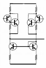
In the middle of + and - supply rails there is a subcircuit consisting of a BD139/BD140, two zeners, ono resistance and two caps, is it the supply regulator you talk about for the imput circuit?
Also I want to build your amp, but I cannot buy 100 pieces of 2sc5200/2sa1943 to match, is it strictly necesary to do so? and if I don´t what could happen?
thanks in advance,
regards.
Carlos,
In the middle of + and - supply rails there is a subcircuit consisting of a BD139/BD140, two zeners, ono resistance and two caps, is it the supply regulator you talk about for the imput circuit?
Also I want to build your amp, but I cannot buy 100 pieces of 2sc5200/2sa1943 to match, is it strictly necesary to do so? and if I don´t what could happen?
thanks in advance,
regards.
Carlos,
In post #647 you mentioned the "critical 1K5 resistances" in the input circuit. The schematic shows 1K6 for R12 and R13.
How critical is this value? I would like to use 1K5 Audiophile resistors there.
billabong.
In post #647 you mentioned the "critical 1K5 resistances" in the input circuit. The schematic shows 1K6 for R12 and R13.
How critical is this value? I would like to use 1K5 Audiophile resistors there.
billabong.
As for matching.... distortion will go down the closer it is matched...
For prototypes, I use a mix of transistors to make sure it is stable down to a worst case scenario... so you don't HAVE to match...
For prototypes, I use a mix of transistors to make sure it is stable down to a worst case scenario... so you don't HAVE to match...
Nordic,
I asked a similar question earlier and either yourself or Carlos recommended that matching the complementary input pair would be a good idea. Is it also the case here that matching would be helpful but not mandatory? Further, I don't know much about matching except that there are different forms of matching... What should a person aim to match here? Vbe? It seems that the small signal input transistors would be much simpler to match and much cheaper to purchase a large quantity. What are your recommendations for a typical limited budget DIYer?
Thanks,
Ryan
Yep matching the little ones on the front is recommended for matching as they influence DC offset, if you are only going to use a multimeter for this, allow them a few minutes to cool down, you will notice just touching them changes the reading... you can easily buy 50 to match probably for $5 if not less
Nordic wrote about C7:
Nordic, I hope you are using a 16V cap for C7 in your prototype, as the BOM lists it as 16V.
I've ordered Black Gate Standard 470uF 16v for C7. They are 12.5mm diameter, which neatly fits the footprint of 13mm diameter.
billabong.
The footprint for the cap you are discussing will handle 1000uf easily,especially as it can even be a16v unit to the best of my knowledge.
Nordic, I hope you are using a 16V cap for C7 in your prototype, as the BOM lists it as 16V.
I've ordered Black Gate Standard 470uF 16v for C7. They are 12.5mm diameter, which neatly fits the footprint of 13mm diameter.
billabong.
Yep I used 16V... and it did not blow up yet...
Sorry Chalo, missed your other question.... The components you talk about combines a zener regulator and a capacitance mulitplier (the cap's value multiplied by the transistor gain)
Sorry Chalo, missed your other question.... The components you talk about combines a zener regulator and a capacitance mulitplier (the cap's value multiplied by the transistor gain)
- Status
- Not open for further replies.
- Home
- Amplifiers
- Solid State
- Dx Precision, finally released... now debugged and better than HRII