Well, dear Nordic, we can arrange the rail regulators.
Also i can tweak it to use 70 volts plus and minus, this way you will be able, also forum folks, to use two 35 plus 35 volts supply to constitute a single 70 plus 70 volts supply...hummmmm, not sure...but maybe this will increase the transistor number...maybe 4 pairs...i have to simulate.
Also we can introduce the transistors you want.... the exception are the drivers...those plastic ones are beautifull, easier to use, do not need insulators, are not addicted to oscilate too...but of course, people is free to use whatever they want...including you dear nephew.
I cannot test, this is the second problem, with those different transistors.... you can use the MJL if you prefer... and we can also include it into the schematic.
I will be out for a couple of hours, will go downtown to buy transistors and solder...will be back, and if you want we can make the 70 plus 70 volts with the rail regulators.
I have asked you what you suggest...finally you said some!
Confirm, clearly, what you want..and i will do it to make you happy...you are partner, you are a friend and you deserve that.
regards,
Carlos
Yes you need 4 pairs for 200W at 8 ohm... the article explains at great lenght how they got to that answer useing SOA curves...
But lets leave the amp as is for now... I just thought if we could power the frontend useing the supply from the output side... regulated down to 55V, it will get much cheaper than buying two transformers...
But lets leave the amp as is for now... I just thought if we could power the frontend useing the supply from the output side... regulated down to 55V, it will get much cheaper than buying two transformers...
Man, be clear to your uncle...do you want or you do not want?
I cannot understand those sophisticated words.... be clear please.
Eu falo Portugues ô amizadinha...num enrola!
I talk portuguese my little friend..do not confuse me please!
Say.... ME WANNA....me do not wanna...ahahahahah
regards,
Carlos
I cannot understand those sophisticated words.... be clear please.
Eu falo Portugues ô amizadinha...num enrola!
I talk portuguese my little friend..do not confuse me please!
Say.... ME WANNA....me do not wanna...ahahahahah
regards,
Carlos
I have simulated... resulted in 200 watts RMS over 8 ohms
undistorted, continuous tone.
the rail regulator can be into the power amplifier board, or included into the power supply board.
I can arrange that if needed.
The difference is the fourth pair of transistors, as more than 340 watts will be possible into 4 ohms and this rail regulator.
Condenser will be into the supply board and into the amplifier left side (input side)
regards,
Carlos
Attachments

sometimes I use this if I have to read some exotic language, it works good for the languages i use like from german and stuff..
Just cut and paste and [traslate]
http://translate.google.com/translate_t?langpair=en|pt
hehe you could try write something in portugese, and we could translate.. :-D
..
hmm oh and about what I was thinking using lm317 as current source, I guess first thing is they couldnt handle the voltage without doing something, and if connecting several in series they have to be equalized with something like 800k resistor or so..
..
About using 1 xformer, I would maybe use just different capacitor banks and different rectifier for each channel..
Just cut and paste and [traslate]
http://translate.google.com/translate_t?langpair=en|pt
Sim você precisa de 4 pares de 200W a 8 ohm. O artigo explica em grande comprimento como eles tiveram que responder às curvas utilizando SOA.
Mas permite deixar o ampères como é para agora. Eu só pensava se pudéssemos poder utilizar o frontend do abastecimento a partir da saída lateral. Regulamentada baixo para 55V, ele irá obter muito mais barato do que comprar dois transformadores.
hehe you could try write something in portugese, and we could translate.. :-D
..
hmm oh and about what I was thinking using lm317 as current source, I guess first thing is they couldnt handle the voltage without doing something, and if connecting several in series they have to be equalized with something like 800k resistor or so..
..
About using 1 xformer, I would maybe use just different capacitor banks and different rectifier for each channel..
Correct, the article claims 350W into 4 ohms,,,,
1 I just tried to point out that there are input transistors that can live at even 70V.
2 I asked if there is alot to loose/any danger by dropping input section voltage in same way as HRII so we can use 1 transformer.
3 I think we should develop the Big Boy 200W later as maybe a subwoofer or something that needs that kind of power
I need to find the scanner's transformer... then I can scan the article.. I got 2 of the 3 magazines so far... 3rd one just covers construction. I will e-mail it to you later... I know you love looking at amp circuits.
Hi Nordic,
the "front end" amplifier does the voltage amplification.
The drivers and output devices do the current amplification (=buffer).
To get the most economic arrangement, the voltage amp should run from the same voltage as the output stage.
You can separate the two halves and feed high quality power into the voltage amplifier and low quality power into the output stage but the voltages should still be similar.
If you decide to reduce the supply voltage to the voltage amplifier, this limits the output voltage sent to the current amplifier. You have thrown away some of the potential output power capability of the amplifier.
DX confirms this in many of his posts.
There is some advantage in running the voltage amplifier stage from a regulated PSU, but you have to decide what voltage to run it at. Same as the output stage or less or more.
If you choose the same voltage then under what mains conditions should it be the same?
There is a disadvantage to using HV for the voltage amplifier. The output clips first and takes longer to recover and this can be more audible than when the voltage amplifier clips. But we should be designing our systems to never clip so this should not be an issue, but it is!
Re: I have simulated... resulted in 200 watts RMS over 8 ohms
Hi,
550 watts are possible from 70 volt rails into 4 ohm load.
That pile of junk that I posted above runs at that voltage and produces that much power.
destroyer X said:
The difference is the fourth pair of transistors, as more than 340 watts will be possible into 4 ohms and this rail regulator.
Hi,
550 watts are possible from 70 volt rails into 4 ohm load.
That pile of junk that I posted above runs at that voltage and produces that much power.
Precision first!
Nordic, I'm with you on point 3 - let's do the Dx Precision first.
Point 2. If affordable it is of course better to have a separate supply for the input section because it would not be affected by draw-down on high output peaks. With a difference of 63-55=8 volts a regulator will probably work well, but with a drop of only 3V in the HRII regulator I worry that the main supply could drop more than 1.5V at full output. (I'm guessing that the regulator needs to drop at least 1.5V to maintain good regulation).
Francois
Nordic said:
2 I asked if there is alot to loose/any danger by dropping input section voltage in same way as HRII so we can use 1 transformer.
3 I think we should develop the Big Boy 200W later as maybe a subwoofer or something that needs that kind of power
I
Nordic, I'm with you on point 3 - let's do the Dx Precision first.
Point 2. If affordable it is of course better to have a separate supply for the input section because it would not be affected by draw-down on high output peaks. With a difference of 63-55=8 volts a regulator will probably work well, but with a drop of only 3V in the HRII regulator I worry that the main supply could drop more than 1.5V at full output. (I'm guessing that the regulator needs to drop at least 1.5V to maintain good regulation).
Francois
I am needing a good friend to produce decent schematic to me.... for the Precision
It seems this model will be the last.....well.... i hope so.
The rail regulator included, it is using 3 output pairs (not shown into the schematic (I could not...was too much ugly..a mess)... a switch as option to connect the power output to the feedback line or not to connect it to the feedback line.... or to have one connected to the feedback line and the speaker out from the feedback line.
A single voltage supply, that can be something from 50 volts to 63 volts simetrical (needing adjustment into the rail zeners to match your special supply).
Standard supply is 63 volts...others can be used....if you will use other voltage, each case can be studied separatelly...board will be a single Precision model...one board model only...how many output transistors you will solder there will depends your supply and your desire to have 3 pairs or less pairs.
This one will continue to provide something around 163 watts RMS over 8 ohms.... minimum, continuous, sinusoidal, undistorted power.
Atention...schematic not showing 3 output pairs...but the amplifier uses three output pairs.... and could be better to use 4 or 5 pairs...we are considering 8 ohms safe operation... and less safe 4 ohms operation (not dangerous).
The bypass, decouple rail capacitors, can go from 27N to 220N.... you can change them in acordance the values you find easier and cheaper in the part's market..they are not critical..only to drain HF and to cancell the electrolitic condenser inductance....a low impedance patch to ground only.
A good friend to produce a nice schematic...someone alike TODD, will be very good.
Nordic..dear nephew... wanna see your smile...wanna see you happy..the regulator you asked is now standard... you tell me and uncle do for you ...immediatelly!
regards,
Carlos
Attachments
Niklas, my dear sweet sweedish friend
Alike happened into Brazilian schools, when one day the teachers, living internal revolution. filled with sad and disgusting feeliing about the students performance... they said!
- No more damn calculators here!...those things are creating idiots!"
So, no more electronic calculators...they are free to be use...out from the school!!!
Inside the school...pencil and papper and operations using brain and hands.
So... dear Nikolas..... Nikwall, chip amplifiers, LM317 regulators, well dear friend...this is calculator...the guy do not calculate nothing, do not learn nothing...i really prefer to teach (already done) how to calculate those simple regulators and CCS and give to them the tool to design that stuff by themselves...
Not to give them a fish to eat each day...to give them the knowledge to fish, to catch their fish daily..to teach them to know how to do.
thank you by your suggestion..it is clever, but against the Philosophy that started Dx threads..the idea is to show them how to do, to understand how to do..not to give them black boxes will already done things.
There are skilled folks in this thread, but a lot of beginners too.... very few designer with your quality around..it is a honor your presence, but you may feel this place a little bit boring for you.
regards,
Carlos
.........................................................................................................
How are you doing Todd?
ahahahahahah
regards,
Carlos
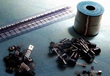
I was out..buying some parts into local shops
40 BC556C
20 BD139 and BD140
20 TIP41 and TIP42
1 Pound of solder
22 electrolitic condensers, Hitano, 100uf/63 volts.
Those folks are use to prototypes till 50 plus 50 volts...i use to burn a lot of them...the BC546C was already provided by Nordic.
My god!....50 bucks!!!!... means 50 US Dollares
Transistors from Fairchild and STI...matched ones...good gain
Solder is normal 60 by 40 ratio of metalic elements into the composition.
regards,
Carlos
......................................................................................................
Good Nordic...send em to me...those magazines.
I have a lot of Aussie magazine amplifiers here.... will upload to you during this weekend.
Nice amplifiers, good images.... those Aussies are great!
regards,
Carlos
......................................................................................................
Niklas, those translator do not produce a good job...i could not understand..words have many meanings, and sometimes the translators produce non sense ideas.
thank you,
regards,
Carlos
Attachments
Hi Charly, Yep, sorry I woke up a little grumpy today, I suspect the topic we are discussing via e-mail has depressed me a little...
I will look at the new schematic a little later so I have time to go through it carefully... I much appreciate the extra work.
Hi Andrew, Yes I'm aware that lower voltage amplification voltage stage can only drive the outputs to the voltages provided by the front.... But I suspect carlos did this as a way to buffer the voltages on the front from dips due to output peaks...
The design was allready centred around 55V input stage... I just believed (I understand a seperate front supply is superior), that there could be quite a saveing on rather just regulateing the output sides voltages to the 55V...as per design.... It will save money on extra transformer, and if you are going to buy a case, one that has space for 2 trannies will probably also be more expensive... Think third world economy design for first world audio enjoyment.
Worst than the sad conversation we had yesterday is the hot here
Man.... i am nude inside my appartment with ventilator running directly on my wet body...a lot of showers i had today.
It is terrible the weather today.... extremelly hot.
When we feel without confort.... so hot this way..we forget our sadness for a more terrible feeling.
The heat is cooking my brain....not to say other more obvious parts.
regards,
Carlos
its going to be a HOT summer....
Luckily the winter is reluctant so far to lets its grip go here... but the few sunny days so far have been boiling too.
Luckily the winter is reluctant so far to lets its grip go here... but the few sunny days so far have been boiling too.
All that is required are a pair of 5Vac low current windings added to the main toroid. Use either 0.5mm or 0.6mm diameter enameled copper wire.Nordic said:The design was already centred around 55V input stage... I just believed (I understand a separate front supply is superior), that there could be quite a saving on rather just regulating the output sides voltages to the 55V...as per design.... It will save money on extra transformer, and if you are going to buy a case, one that has space for 2 trannies will probably also be more expensive... Think third world economy design for first world audio enjoyment.
eg, 40Vac + 40Vac @ 5A becomes 40Vac+40Vac @ 5A and 45Vac +45Vac @500mA. A bridge rectifier on each of the 45+45 gives the high voltage low current supply for either a simple PSU or a cap multiplier or a regulated PSU.
Friends,
Put some heavy winter cloth on you and come visit as in Romania! We will welcome you with "cozonac", a traditional Christmas cake.
http://carollingineurope.wordpress.com/2007/12/23/romanian-christmas-recipe-cozonac/
Mihai and Andrei
Put some heavy winter cloth on you and come visit as in Romania! We will welcome you with "cozonac", a traditional Christmas cake.
http://carollingineurope.wordpress.com/2007/12/23/romanian-christmas-recipe-cozonac/
Mihai and Andrei
Attachments

Re: Worst than the sad conversation we had yesterday is the hot here
Be cool, man. We can't afford to loose that brain!
BTW, how hot is "extremely hot" at your location in Brazil?
Francois
destroyer X said:
It is terrible the weather today.... extremelly hot.
regards,
Carlos
Be cool, man. We can't afford to loose that brain!
BTW, how hot is "extremely hot" at your location in Brazil?
Francois
Boys.... i have mail from Aspen Amplifiers.... Santa Klaus from Kangaroo country sent
Boards.... some ideas he had...not his line...his brain storm.
I am crazy to see them
I have Roender amplifier to make into the first moment...i have finished my Techno by Bora, my HRII and a Prototype from Precision and Precision II also.
Soon i will be building Roender hiper clever schematic.... Field effect transistors arrived from Nordic.
Regards to François, also to Roender.... hello to Andrew...long time without receiving Andrew t visit.
People told me the Precision is expensive.....maybe, but we can make some reduction in costs...in special Dx crew that already have two transformers to use...just disconnect from the Dx Standard, or HRII amplifier you have and can use it to listen the Precision...
Here a sketch...how to use them together.
regards,
Carlos
.......................................................................................................
François
Very hot here is when temperature reach 32 degrées celsius into the appartment.... so...not under the sunligth, and when the wind stopped.
regards,
Carlos
.......................................................................................................
Roender
You are a very respectable designer... your intelligence is clear for us...a big honor to me to eat that Cozonac with you and to produce picture together you to show my Brazilian friends i could be together a gênius for some moments (till the one discover how weak in knowledge i am compared with your knowledge)
regards,
Carlos
Attachments
I don't think the precision is so expensive.. it costs what it costs...
6 pairs of output transistors will cost 3 times what 2 pairs cost...
I will likely still use 100V caps... as overspecing voltage is the way I have been tought... shame they are so big and expensive... but it is a choice...
When I look at the Studio 350 amp, it has only one relatively small pair of caps for the 8 transistor output....
Someday when my hearing goes bad enough, for it not to make that last bit of effort worthwile, I will start useing small caps too 🙂
Lucky you, Hugh sends you all the good stuff... at the current rate I can maybe afford one of his starter models by the time I hit 50.
- Status
- Not open for further replies.
- Home
- Amplifiers
- Solid State
- Dx Precision, finally released... now debugged and better than HRII