Nordic said:You need to reduce one of the resistors to increase the gain (I think R4), and increase the sensitivity.
The gain factor is determined by R3 and R4, and it is like so :
Ku=R3/R4+1
So that is correct, you can increase the gain by reducing R4, but as you do that you will have to increase C7 to save the time constant R4*C7=T.
The other option is to reduce R3, but doing so will result also with some other factors - R2 has to be reduced to the same value, and with that you'll have to tweak C6 a little bit for the same reason - to observe the time constants, wich are key components of the silence - thumps, on/off transition processes, and so on ... 🙂
This is an error, may slow down the amplifier.
You can de activate this replacing the resistance R9 to a 820 ohms, or reducing C10 to 10 ohms..... i found the amplifier stable not needing that stuff.... you can even remove or R9 or C10...if you prefere can remove both.
Big resistances (dissipation, heat) under the board are not a very good idea, the emitter resistances under normal operation do not produces too much heat, but even those must be soldered distant from the boards.
Heat goes up, as convection current and needs room, space, free air up to travel, to go up.... if they find a board up, they will heat the board, heating the board will transfer heat to parts and transistors are heat sensitive, so, it is better, and more safe, not to transfer resistances to be used down the boards.
The ones are under the board where needed solutions, easier solutions taken during the board design, but they are not the best possible solution... i do not even remember if i made the ship or was something Nordic needed to do.
Well, emitters resistances are already there..... assemble them distant from the board.
regards,
Carlos
Attachments
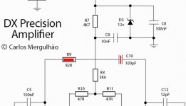
This condenser, the smaller the value the better the treble
Also if you have some belief better capacitor value sounds better, then install a Silver Mica in this position..... Silver Mica is said to be more stable, and some folks say it sounds better.... this depends you beliefs.... will make you happier to make what you believe.
After building and debugging.... when finding the amplifier stable, already adjusted and playing, then you can tweak reducing this condenser value, and the quality of treble will be perceived clearly as increasing.....but you have to be monitoring the output.... plug an AC voltimeter into the output and check if you do not have AC there when have no audio entering the amplifier.
Much better is to inspect using a Scope, as some oscilations starts triggered by the audio signal, some of them of short timing...and this you need the scope to observe.
Reduce as much as you can.... and you find oscilations, then increase the condenser two steps up related the sequence of capacitor values.
Alike; 10pf, 12pf, 15pf, 18pf, 22pf, 27pf, 33pf, 39pf, 37pf, 56pf, 68pf.... so, if you have oscilations using 18pf, for instance.... then use 27pf (2 steps up for safety reasons)
This capacitor, despite needed, produces an effect (defect) to triangulate wave shape.... when you inject sinusoidal and go increasing frequency, the signal will go triangle into frequencies around 50 kilohertz when this condenser is too much big.... when not big, the triangulation happens into frequencies bigger than 80 kilohertz.
Normally this condenser, with reasonable values, do not triangulate frequencies into the audible range, but we feel the efect... do not ask me how and why because i do not know...you do not have effect into the wave shape when the value is big, but you perceive losses of quality into the high end.
It is a good thing to test by yourself and to learn one of the most sensitive parts into amplifier construction.
regards,
Carlos
Attachments
Optimizing the Precision Performance step three
The input condenser can be reduced to 220pf, this will turn treble a little bit more clear as very high frequency will be free of interferences.... some high frequency harmonics that produces enrichment into the sound will be more present.
I am not able to listen high frequencies, as i am not young anymore, but some of you may have those benefits.
The gain resistance must be adjusted to have distortions when you have adjusted your pré amplifier volume, or audio source volume, to 75 percent of maximum volume.
Errors produces compressed and noisy audio....or, in the other extreme you will never drive the amplifier into it's maximum power.
The amplifier was not created to receive sound from Ipod, MP3 player, MP4 player or anyone of those toys... reason why the sensitivity was made to 750 milivolts RMS to full power.... not sure if this was respected into the schematic as Nordic use to ask more sensitivity to his audio source....i will check....but, you already know..... your volume must be around 75 percent to start distortions, clipping... this is the best possible adjustment, as you will have room to increase some music programs that have slow levels and will be able to use the amplifier full power.
regards,
Carlos
Attachments
It is all rigth...the gain resistance is fine
With 750 milivolts you drive the amplifier to a high power, almost touching the undistorted limits.
As audio sources have more than 750 milivolts, we have the guarantee that we gonna have a little bit of clipping... so the 75 percent of volume will work fine.
Ipod, MP3 players and MP4 players needs an interface, a load resistance and a big condenser to avoid saturate the amplifier with residual signal from digital processing... Precision I will not sound fine without input interface, loading resistance and 2N2 capacitor to ground.
regards,
Carlos
Attachments
Public apologize folks...i am an idiot
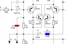
The input condenser is terrible wrong..... the correct value is 1uf, and i made into the schematic 10 times bigger... and worse, an electrolitic condenser there.
Please, reduce it to 1 uf or a little bit bigger to have the normal 3dB losses into 20 Hertz as is standard to the Amplifiers industry.
Also, use 220N (0.22uF) if you will use it with a turntable, as the humble, the non filtered humble will waste power and will overheat the unit.... this is to reduce, and a little, the humble low frequencies...but please, use the humble filter you may have to use it with Vinyl discs.
regards,
Carlos
Attachments
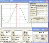
Now i have better tools to work... a new simulator
updated, and the best one i think.
Now i can produce more detailed tests.
This helps a lot.... listening i use to make my decisions, but some doubts can be answered by simulators..... alike the best input condenser and those things.
regards,
Carlos
updated, and the best one i think.
Now i can produce more detailed tests.
This helps a lot.... listening i use to make my decisions, but some doubts can be answered by simulators..... alike the best input condenser and those things.
regards,
Carlos
Attachments
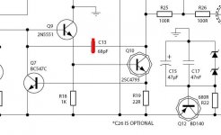
Negative TAJ, no hug about that subject
The 2 watts resistance i have here do not turn hot when operating in the Precision.
Maybe new resistances works hot...so.... not really 2 watts resistance in my point of view.... those ones are 2 watts heaters.
ahahahahaha.
People is needing bigger watt resistance because using material specified wrongly.... if the 2 watts resistance works hot when dissipating 2 watts, means it is not really dissipating 2 watts.
The ones will work hot, down here in Brazil, will be the 1/4 watts resistances only...when submited to stress!
2 watts resistances made in Brazil are big.... off course, need area to dissipate 2 watts without be hot!.... those modern fooling units i really do not know.... maybe you will need to buy a 100 watts to work cool...hehehe..... transported by a truck!
So, if i could understand, they are making 2 watts resistances that will not burn themselves when working with 2 watts, but the material will not melt under the extreme high temperatures....heheheh..better to buy brazilian resistances.
regards,
Carlos
hi,
thank you. i understnad that i sould not change anythings in the circuit as it is working fine to me. can i add a gain circuit for this amp? what is max gain should be enough for the prcs-I?
i know my cd player has very low gain out put. i need to add a gain increse circuit.
thank you again.
thank you. i understnad that i sould not change anythings in the circuit as it is working fine to me. can i add a gain circuit for this amp? what is max gain should be enough for the prcs-I?
i know my cd player has very low gain out put. i need to add a gain increse circuit.
thank you again.
Dx Corporation provides you an automatic leveller, adjuster
sensitiviter adjustment tool.... free for you!, do not need to purchase!
And with 100 percent discount refered to the standard price offered to consumers!
The super hiper automatic gain increasing tool!
Easy of adjustment!
You do not need to be tired adjusting!
Operating automatically do not need bateries!
Make fast your adjustment!
heheheh.... kidding.... remembering the brain wash advertising on satelite television, Discovery channel and history channel for instance...ahahahahahah.
Decrease this resistance to increase your gain, your sensitivity, when your CD player has not too much audio output level.
Increse this resistance to decrease your gain, your sensitivity, when your CD player had too much big audio output level.
be happy.
Carlos
Attachments


space, CD players usually have an output of around 2Volts, so the 750mv input sensitivity of the P1 means you would need something to lower the voltage, such as a preamp or other interface, such as a volume control.
found the fault.....
Dear friends DX and all,
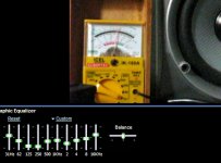
I have found the sound I suppose to get from precision-I. It is delivering clear and wonderful sweet sound. I have found the fault, Equalizer setup. My equalizer is 27band graphic so needed to adjust for the output.
I am now listing Beautiful clear and sharp sound more then my mobile. No any problem arises until now.
Very nice…
I will setup in proper way. Will show pic of my speaker and others devices too.
Thank you very much for helping me.
Best regards
michael
Dear friends DX and all,
I have found the sound I suppose to get from precision-I. It is delivering clear and wonderful sweet sound. I have found the fault, Equalizer setup. My equalizer is 27band graphic so needed to adjust for the output.
I am now listing Beautiful clear and sharp sound more then my mobile. No any problem arises until now.
Very nice…
I will setup in proper way. Will show pic of my speaker and others devices too.
Thank you very much for helping me.
Best regards
michael
Re: Public apologize folks...i am an idiot
Interesting Carlos.
Is the C-IN acting as a 1st order filter, or a more complicated network? What value cap would I use to obtain -1db at 10Hz, or -3 at 5Hz? These roll-offs are more typical of high-end amplifiers. (mostly still flat at 20 Hz.)
No, I can't hear that low, and my speakers cannot go that low, but I'm sure it bothers the ants, so it's worthwhile.
Also, a minor English correction: it's *Rumble*. Humble means something like 'no bad ego problem'. You are humble, my friend, and maybe you rumble too. Your English is getting amazingly good now Carlos. It's time to start fine tuning it -- tweaking it a little. You are ready for that now.
..Todd
destroyer X said:
The input condenser is terrible wrong..... the correct value is 1uf, and i made into the schematic 10 times bigger... and worse, an electrolitic condenser there.
Please, reduce it to 1 uf or a little bit bigger to have the normal 3dB losses into 20 Hertz as is standard to the Amplifiers industry.
Also, use 220N (0.22uF) if you will use it with a turntable, as the humble, the non filtered humble will waste power and will overheat the unit.... this is to reduce, and a little, the humble low frequencies...but please, use the humble filter you may have to use it with Vinyl discs.
regards,
Carlos
Interesting Carlos.
Is the C-IN acting as a 1st order filter, or a more complicated network? What value cap would I use to obtain -1db at 10Hz, or -3 at 5Hz? These roll-offs are more typical of high-end amplifiers. (mostly still flat at 20 Hz.)
No, I can't hear that low, and my speakers cannot go that low, but I'm sure it bothers the ants, so it's worthwhile.
Also, a minor English correction: it's *Rumble*. Humble means something like 'no bad ego problem'. You are humble, my friend, and maybe you rumble too.
Your English is getting amazingly good now Carlos. It's time to start fine tuning it -- tweaking it a little. You are ready for that now. ..Todd
Maybe wrong TAJ, was something written into old amplifiers panels
Was a switch, to cut (attenuate) low frequencies generated by turntables... alike hum produces the sound of low frequencies from supply or because of bad shield into audio cables, the humble word is the sound equivalent of the noise produced by turntable motors spinning.
I will search for it my dear.... maybe written in other way...but humble is something existed.
In your language you have a lot of words that "sounds" alike the sound the "thing" produces.... this is very interesting thing you have in your language, we have proper words to each sittuation, but i really like this way to make the sound by ourselves.
Will search for 3db into 5 hertz to you my dear.
On time... correct dear TAJ..... Rumble is written using "R"... sorry to try to destroy your language.
regards,
Carlos
Attachments
Re: Re: Public apologize folks...i am an idiot
I much prefer the sound when using F-3dB<=2Hz and have settled on using input filter set to 90mS (F-3dB=1.8Hz). I use the same filtering for amplifiers feeding bass only speakers and for Sub-bass speakers.
for 90mS the R & C components are simply multiplied together to obtain the RC time constant.
i.e. Zin=47k and Cin=2u2F gives RC=103mS (47,000*2.2^10-6=0.103).
Remember, that the DC blocking capacitor in the source must be taken into account if both capacitors are operating as high pass filters. i.e series caps add like resistors in parallel.
For F-3dB=1.8Hz (RC=90mS) to work correctly, the NFB RC must be set to >=130mS and the PSU RC must be set to >=180mS. i.e. smoothing capacitance per channel >=+-22mF for 8ohm speakers.
using small speakers that roll off @ 60Hz, I can hear the difference between F-3dB=8Hz and F-3dB=2Hz.taj said:What value cap would I use to obtain -1db at 10Hz, or -3 at 5Hz? These roll-offs are more typical of high-end amplifiers. (mostly still flat at 20 Hz.)
No, I can't hear that low, and my speakers cannot go that low, but I'm sure it bothers the ants, so it's worthwhile.
I much prefer the sound when using F-3dB<=2Hz and have settled on using input filter set to 90mS (F-3dB=1.8Hz). I use the same filtering for amplifiers feeding bass only speakers and for Sub-bass speakers.
for 90mS the R & C components are simply multiplied together to obtain the RC time constant.
i.e. Zin=47k and Cin=2u2F gives RC=103mS (47,000*2.2^10-6=0.103).
Remember, that the DC blocking capacitor in the source must be taken into account if both capacitors are operating as high pass filters. i.e series caps add like resistors in parallel.
For F-3dB=1.8Hz (RC=90mS) to work correctly, the NFB RC must be set to >=130mS and the PSU RC must be set to >=180mS. i.e. smoothing capacitance per channel >=+-22mF for 8ohm speakers.
TAJ, i have simulated and 1uf did exactly what you wanted
3db losses of power into 5 Hertz.
Amplifiers was adjusted to maximum swing without clipping at 1 Kilohertz and them frequency was reduced till the loss you wanted...and exactly 1 uF..... so, the suggested value is precise.
The ones wants to obbey those rules, search for a good non polarized capacitor, with sneak oil or without it.
BTW dear TAJ.... this is a highly bureaucratic worry....nobody is able to listen 5 hertz or something.... we can feel room shacking and not more than that.... this means, energy wasted reproducing something that serves only to make dust to dance.
My problem is to make people dance!.... a hell to the dust and wasted energy to make wall panels to shake....but i know...there are folks that loves to feel the house shaking.... well....to them my best wishes that they can be happy with their demolition, the Precision is very good to do that.... just install 47 uf into the input that you gonna have a very crazy bass.
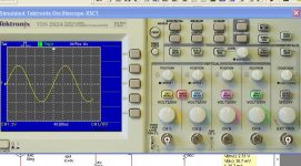
I have a movie, made with the Precision, speaker moving into 5 hertz, a sinusoidal signal.... it is into youtube.
regards,
Carlos
3db losses of power into 5 Hertz.
Amplifiers was adjusted to maximum swing without clipping at 1 Kilohertz and them frequency was reduced till the loss you wanted...and exactly 1 uF..... so, the suggested value is precise.
The ones wants to obbey those rules, search for a good non polarized capacitor, with sneak oil or without it.
BTW dear TAJ.... this is a highly bureaucratic worry....nobody is able to listen 5 hertz or something.... we can feel room shacking and not more than that.... this means, energy wasted reproducing something that serves only to make dust to dance.
My problem is to make people dance!.... a hell to the dust and wasted energy to make wall panels to shake....but i know...there are folks that loves to feel the house shaking.... well....to them my best wishes that they can be happy with their demolition, the Precision is very good to do that.... just install 47 uf into the input that you gonna have a very crazy bass.
I have a movie, made with the Precision, speaker moving into 5 hertz, a sinusoidal signal.... it is into youtube.
regards,
Carlos
I will upload the video to you dear TAJ
off course you will hear nothing.... this frequency only for whales.
But i use to show the sinusoidal movement into the speaker to young boys.. attaching a pen into the diafragm and moving a paper you will have the sinusoidal wave into the papper.
This way they can see the graphic, observe the "time" because they have to control manually the speed of the paper rolling and the analogic meter shacking and also the effect... the speaker moving showing the result of sinusoidal tone.
Oh!... my students use to evolute very fast.... my people is clever.
regards,
Carlos
Attachments
P1 input filter: Solid state Power amplifiers usually have a response down to a few hertz, even zero. Any response roll-off is usually achieved at the source, such as a Phono Preamp, sometimes required when using a Turntable. Intergrated amplifiers having a phono input will usually have a roll-off of 3db at 20-30HZ. Todays Audiophile turntables have very low levels of rumble, and do not need a rumble filter, except when unresolved low level signals are generated by cartridge/tonearm/ support compliance issues.
Even my 1960s Garrard 301 turntable, properly overhauled, plinthed and supported, has inaudible noise.
billabong.
Even my 1960s Garrard 301 turntable, properly overhauled, plinthed and supported, has inaudible noise.
billabong.
- Status
- Not open for further replies.
- Home
- Amplifiers
- Solid State
- Dx Precision, finally released... now debugged and better than HRII