Your calculations are wrong Nordic.
Please, check your calculations and do not try to produce doubts here.
Power is voltage multiplied by current.
Rail to rail is 64 plus 64 volts.... in the reality lower than that.
so.... 128 volts maximum (real is lower than that)
Ohms law..... E=I x R..... so, current over 10.000 ohms (E/I) is
12.8 miliamperes (0.0128A)..... if you have this current flowing inside a resistance that has 128 volts (has less than that) your result will be (voltage multiplied by the resistance) 1.69 Watt.
Man..... the one use to correct folks is Andrew.... not nice but at least he is a Master....you have made some boards and have readed some papers and will start to correct people calculations too?
Already made what you want...the awfull big resistance...a giant one... changed because your errors in calculations... the only needed thing with the correct designed resistance is to put it distant from the board as Professionals do with power resistances....now you want to convince people of 8 watts?
Please....you made boards, not the design.
Sorry folks to be a little bit rude and abrasive....but there are some limits to face those things.... and about those things, related Nordic, patience is finishing.
Carlos
Hi Carlos isn't rail to rail +&-55V (i.e. 110V) after the zener regulators? (22 + 33V)
I added a 5% margin for the zeners, this should have been 10%, I forgot about the negative rail... so it could WORST CASE come to 121V Rail to rail
I added a 5% margin for the zeners, this should have been 10%, I forgot about the negative rail... so it could WORST CASE come to 121V Rail to rail
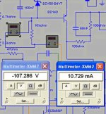
In the reality, observing the real voltages into the simulator
The power dissipation over this 10K resistance is 1.2 Watts.
Power is the result of the multiplication of voltage expressed in Volts by the currente expressed in Amperes.
So, 107.286V multiplied by 0.0107A will result in 1.15 watts
I have asked Taj to put 3 watts (the whale resistance) because of your Mathematics.... if not wrong, at least different from my Mathematics.
I am sorry to be rude and with the lack of patience, but i do not regret to correct Nordic about such things.... i found, discovered, today, the Dx Amplifier and beeing sold by pirates into National Ebay (alike Ebay, a local, brazilian free Market).
No one will feel good with that...for sure.
regards,
Carlos
Attachments
You got to 1.15W, my earlier calcs came to just short of 1.2W... hardly a diffirence...
Useing my correction....
The 10K does not connect rail to rail but to the bottom of the 4.7V zener, which must thus be deducted from the 121V absolute available max voltage, useing 55V zener regulators of 5% tolerance. ( I am not sure if one should add or subtract the .7V Vbe in the two transistors in the regulators)
121-4.7= 116.3V
/10k = 0.01163A
= 1.353W
This 10K resistance will dissipate less than 2 Watts
The schematic will suggest folks to use 3 watts to have some room.
Your board, your own circuit, if you like, you can put 50 watts resistance and connect it to the air conditioned or to ice bars.
But please, do not generate doubts Nico, your responsability is about the boards you have made...already a very big responsability....let the design responsability to me.
Your comments are already in excess about this subject.
regards,
Carlos
Re: In the reality, observing the real voltages into the simulator
Carlos, I looked for fake DX amps being offered on "Mercado Livre" and could not find any.
Could you point me on the right direction?
I want to ask the seller where he got the schematics from...
I wonder if he/she is using Nordic's board layout too...
destroyer X said:
...
.... i found, discovered, today, the Dx Amplifier and beeing sold by pirates into National Ebay (alike Ebay, a local, brazilian free Market).
No one will feel good with that...for sure.
regards,
Carlos
Carlos, I looked for fake DX amps being offered on "Mercado Livre" and could not find any.
Could you point me on the right direction?
I want to ask the seller where he got the schematics from...
I wonder if he/she is using Nordic's board layout too...
Re: This 10K resistance will dissipate less than 2 Watts
Hi Carlos,
I should agree with Nordic.
A 3W resistor's surface temperature will reach ~100°C when dissipating 1.2W at the normal (25°C) ambient temperature.
Than for 1...1.5W constant dissipation it's a better idea to choose an 5W rated resistor!
Keep the parts cool!
All the best,
destroyer X said:
The schematic will suggest folks to use 3 watts to have some room.
Your board, your own circuit, if you like, you can put 50 watts resistance and connect it to the air conditioned or to ice bars.
But please, do not generate doubts Nico, your responsability is about the boards you have made...already a very big responsability....let the design responsability to me.
Your comments are already in excess about this subject.
regards,
Carlos
Hi Carlos,
I should agree with Nordic.
A 3W resistor's surface temperature will reach ~100°C
when dissipating 1.2W at the normal (25°C) ambient temperature.Than for 1...1.5W constant dissipation it's a better idea to choose an 5W rated resistor!
Keep the parts cool!
All the best,
I will use 5W Mills resistors for R16. They are nice and small, only 4mm (D) x 14mm (L). Carlos will love these.
billabong
billabong


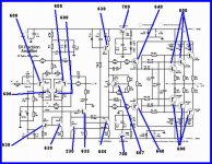
Chances for human errors increased a lot into Precision I
I really think it is not to beginners, because more parts confuses and increases changes to mistakes.
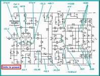
Because of that, i have made Charts, not so pretty as i have dreamed, but something may help to check your amplifiers.
Those voltages, and currents, depends from the supply voltage, the material to be shown here is result of simulation, and using 64 volts as supply...and the rail regulators reduced to 54 volts or something around that.
Simulator is simulator.... reality is reality.... some measurements may differ 20 percent plus and minus...but, even this way this is a very good reference as when we make errors all voltages turns very crazy and very different from this one.... this will be telling you that you have errors into your construction, and this will happens a lot.
Use all zeners to 1 watt to be into the safe side...some of them do not need that...but for safety reasons and to make things more simple...all them 1 watt.
Three charts, one showing voltage to ground.... second one showing VBEs and third one will show you some currents into the stand by mode.
Please, this is not precise...do not have the spectation to find exactly the same voltage.
Carlos
I really think it is not to beginners, because more parts confuses and increases changes to mistakes.
Because of that, i have made Charts, not so pretty as i have dreamed, but something may help to check your amplifiers.
Those voltages, and currents, depends from the supply voltage, the material to be shown here is result of simulation, and using 64 volts as supply...and the rail regulators reduced to 54 volts or something around that.
Simulator is simulator.... reality is reality.... some measurements may differ 20 percent plus and minus...but, even this way this is a very good reference as when we make errors all voltages turns very crazy and very different from this one.... this will be telling you that you have errors into your construction, and this will happens a lot.
Use all zeners to 1 watt to be into the safe side...some of them do not need that...but for safety reasons and to make things more simple...all them 1 watt.
Three charts, one showing voltage to ground.... second one showing VBEs and third one will show you some currents into the stand by mode.
Please, this is not precise...do not have the spectation to find exactly the same voltage.
Carlos
Attachments
Now voltages from Base to Emitter, the VBE voltages
You must insulate your multimeter probe point and let only a small tip not insulated outside, this is to avoid shorts.... put one probe point into the base and the other probe point into the emitter....adjust your digital multimeter to 2 volts or something alike.
regards,
Carlos
You must insulate your multimeter probe point and let only a small tip not insulated outside, this is to avoid shorts.... put one probe point into the base and the other probe point into the emitter....adjust your digital multimeter to 2 volts or something alike.
regards,
Carlos
Attachments
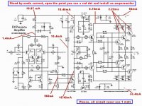
Current measurements are dangerous, as you may open circuit part and will cause
hard and dangerous unballance of voltages and currents that may destroy some transistor...please, do not use it if not hardly needed....only as your last tool to debug your amplifier.
Current measurements are made in series with the circuit... the multimeter must have the plugs changed to the current position that means a short inside the instrument...very dangerous...and them, using small current range, around 200 miliamperes or lower in some sittuations, you will interrupt the circuit and will close circuit once again througth the instrument..... very dangerous...really a problem...you may burn drivers and output.
But, it is there to help you and to check power into resistances and those things.
Remember what old Charlie is informing you.... it is very rare someone to assemble and some amplifier works first try.... we use to produce mistakes...many mistakes each day.
And the worst of the humans is the one thinks can be precise...this is the biggest mistake he is already doing..to think he is super human.
The amplifier was assembled, tested many times...it works.... guaranteed..if something do not result fine... for sure, i can guarantee you made some sheet.... check the sheet of paper...ahahahaha.
YES!.... current into the positive rail is bigger than the current into the negative rail... this is only during stand by mode.... into operations this difference is not more noticed as means some few miliamperes when you will drive many amperes each rail.
This happens because zeners are using around 5 to 10 times the current needed to the circuit the zener regulators will supply... this is some standard procedure... at least into my backyard laboratories.
regards,
Carlos
Attachments
Sorry to post it here again. really need to know.
Hi,
I need some suggestion about the sound quality and amp using mobile phone and normal CD player.
I don’t know you have tried or not. This is my own experience just I got from my own CD player and mobile phone.
I just made an Dx-prc-I. its sound great means really beautiful when I use my O2 mobile phone to play the song, its like life quality. sound sharp, dynamic, voice is great but when I put on CD player, it’s gets flat sound, quality cut by 70% thou even the same song, loud ness also gets low.
I know mobile phone have an amp on output stage…..
What can I do to use my CD player to have same sound quality? Should I put a op amp or preamp or some things? Or other suggestion pls……
Pls write your suggestion.
Need explanation.
Thank you
Michael
Re: This 10K resistance will dissipate less than 2 Watts
Now now children! Group hug!


destroyer X said:Your comments are already in excess about this subject.
Nordic said:Whatever
Now now children! Group hug!
You need to reduce one of the resistors to increase the gain (I think R4), and increase the sensitivity.
- Status
- Not open for further replies.
- Home
- Amplifiers
- Solid State
- Dx Precision, finally released... now debugged and better than HRII