uncle final scheme? I would like to try darlington amp since i`ve couples of darlington transistor with me, can u make clear schema? i would like to test simulate and assemble it.
regards.
regards.
All right Norazmi...but it is not ready...it is a prototype
So...i cannot guarantee...it is under testing...will make it for you and gonna publish as soon as possible.
Video with instructions to you dear Norazmi, is being uploaded now to Youtube.... soon i will publish it here in the thread.
Here the video:
http://www.youtube.com/watch?v=3bmTz3lFDYA
regards,
Carlos
Attachments
Last edited:
I am trying to reduce the board size
Here you have images attached, there are some minor mistakes to fix.
Also a video explains why i did:
DxDc smaller board size...how to make it - YouTube
regards,
Carlos
Here you have images attached, there are some minor mistakes to fix.
Also a video explains why i did:
DxDc smaller board size...how to make it - YouTube
regards,
Carlos
Attachments
Last edited:
I am starting to prepare the smaller board
Here a video about the start:
DxDc - starting to produce smaller board - YouTube
regards,
Carlos
Here a video about the start:
DxDc - starting to produce smaller board - YouTube
regards,
Carlos
DxDc PCB smaller ?
...... I'm back again with my last PCB project DxDc and I hope I have done right....... Just my little contribution 😉
Regards Alex. 🙂
...... I'm back again with my last PCB project DxDc and I hope I have done right....... Just my little contribution 😉
Regards Alex. 🙂
Attachments
Last edited:
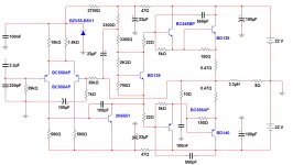
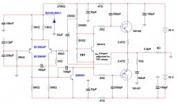
It is not correct dear Alex because i am not using discrete darlington in the output
As i have explained to Norazmi, the schematic is not the final one and i was using discrete transistors because i have no good darlington unit in my simulator..... the reality is that i am using darlington...but people can use the way you made because will work too..they will have to replace the output by a bigger units because BD139 and BD140 will explode if used in this circuit with all that supply voltage..... i was trying to make, to fabricate, to create a darlington.
The amplifier uses darlington in the output dear Alex mm ....so.... despite not wrong, and that can be even used, it is not the correct amplifier.
Also i have the intention to make the board even smaller...i am publishing videos and there you see what i am doing to reduce size.... vertical resistors i am using in order to reduce size.... see some videos if you have time dear Alex....here you have the link to videos:
destroyersoueu - YouTube
A brazilian friend was invited to make the pcboards...he even have made, but i have not published because the amplifier is not ready to go....i am testing for a while...he made the pcboard and i have asked him to hold on till i finish.
You are really fast Alex mm, but seems you have lack of time to be reading....you take schematic and go ahead....the schematic shown was not the one...not correct..... the output is a fake, fabricated, darlington alike style construction, made to substitute the real darlingtons because the lack of these parts in my Multisim 11.0 (Professional full Edition)
I will post another schematic showing the real thing soon....with some small darlington in place to show you the small amplifier it results using these transistors.
regards,
Carlos
Here you have another video, board reduced being painted
Soon it will be corroded (another video) and built (one more video) and tested (and more videos...the way i like).
DxDc - Painting the smaller board - YouTube
regards,
Carlos
Soon it will be corroded (another video) and built (one more video) and tested (and more videos...the way i like).
DxDc - Painting the smaller board - YouTube
regards,
Carlos
As a tradition i use to make one pcboard my style, and always
i use pcboards from cooperative friends...Alex mm is one that is always present and made several of my amplifier's pcboards...very welcome his job to us.
Also Herman, a brazilian friend is doing several projects to help me...he made this suggestion you can see below and i have asked him to wait a little bit and to move the lower condenser to the right side in order to fill the empty space we have downwards and right side.
regards,
Carlos
Attachments
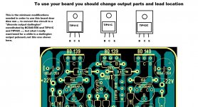
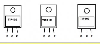
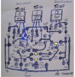
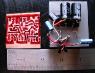
To make your board usefull, dear Alex mm, we must change things
and use it as a discrete darlington output amplifier.... pins must change because BD139 is different compared to TIP41/42.
But what i really want is something made to darlington..with vertical resistors to make it as small as possible (the main idea, the philosophy, is to substitute an integrated circuit by a better discrete design)... the board should be as small as possible...a micro board is what i want.
You see an image with me trying to make your pcboard usefull and another image show the output that i want placed in your pcboard.
thank you,
regards,
Carlos
Attachments
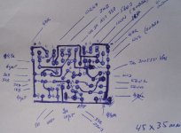
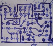
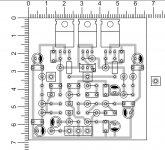
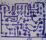
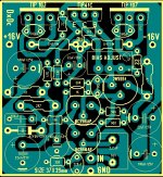
Please Herman and Alex mm, start for mine board as a reference
and make it better and smaller than mine.
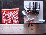
Mine one dimensions are 45 by 35 milimeters....make it smaller (lower image) and better than mine please.
thank you,
regards,
Carlos
and make it better and smaller than mine.
Mine one dimensions are 45 by 35 milimeters....make it smaller (lower image) and better than mine please.
thank you,
regards,
Carlos
Attachments
Last edited:
Great...thank you
I will be waiting....will be very good..for sure will be.
The shape must be the most squared possible...or a rectangle with side's dimension not so different...then gonna be almost a square....small condensers in size because it will be to operate under 16 or maximum of 25 volts..they are very small because of that...resistors of 1/4 or watt because the unit is low power.... 0.5 watt size to the power emitter resistors..and the output coil goes over a 3 watt 10 ohms resistor that is small too.
regards,
Carlos
Last edited:
...... I'm back again with my last PCB project DxDc and I hope I have done right....... Just my little contribution 😉
Regards Alex. 🙂
Alex, what PCB software do you use ?
Also, do you use auto routing ?
@fireworks , my software, it's Sprint Layout 5.0 licenced, with modified library by me acording to my taste . I not use automatic router , only manual , that's the real artwork. 🙂
@Carlos I do my best ,as usual, to layout with small component, and right size of PCB .😉
Regards Alex.
@Carlos I do my best ,as usual, to layout with small component, and right size of PCB .😉
Regards Alex.
Thank you Alex.... small is very important because the idea that is
behind this amplifier is to substitute (with advantages of audio quality) an integrated circuit.
Another idea is to produce something that can be installed inside a small bookshelf.. and this ask for small dimensions and reduced power.... this video here explain you how i decided to make this one:
http://www.youtube.com/watch?v=5i9LV1IJhsc
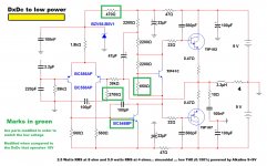
Something able to work with 9 plus 9 volts from AC-DC small outlet converters and even Alkaline batteries to very low volume as a monitoring amplifier.
The amplifier must work with 22 plus 22 volts to 8 ohms loads and do it in a reliable and safe way...also to operate with 16 plus 16 volts accepting 4 ohms and being safe.
This is the main idea..... so, to be small is the most important thing...the use of darlington transistors was the choice to reduce the parts count...to be small.
More important than to be pretty is to be small and reliable.
Posted goes the 9 plus 9 volts schematic to be tested...not approved yet....of course using batteries they will be exausted in a very short time.... this will be tested and evaluated soon.
regards,
Carlos
behind this amplifier is to substitute (with advantages of audio quality) an integrated circuit.
Another idea is to produce something that can be installed inside a small bookshelf.. and this ask for small dimensions and reduced power.... this video here explain you how i decided to make this one:
http://www.youtube.com/watch?v=5i9LV1IJhsc
Something able to work with 9 plus 9 volts from AC-DC small outlet converters and even Alkaline batteries to very low volume as a monitoring amplifier.
The amplifier must work with 22 plus 22 volts to 8 ohms loads and do it in a reliable and safe way...also to operate with 16 plus 16 volts accepting 4 ohms and being safe.
This is the main idea..... so, to be small is the most important thing...the use of darlington transistors was the choice to reduce the parts count...to be small.
More important than to be pretty is to be small and reliable.
Posted goes the 9 plus 9 volts schematic to be tested...not approved yet....of course using batteries they will be exausted in a very short time.... this will be tested and evaluated soon.
regards,
Carlos
Attachments
Last edited:
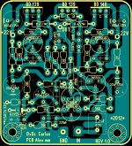
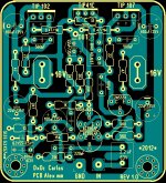
Thank you and congratulations Alexandru.... a beautiful tiny pcboard
very small and compact unit that match our needs.... and have made it smaller than mine.... impressive Alex... very impressive.
Very good.
Carlos
very small and compact unit that match our needs.... and have made it smaller than mine.... impressive Alex... very impressive.
Very good.
Carlos
Last edited:
Impressive what Alexandru did.... i could not make it smaller
I made the challenge.... impressive he has beated uncle this way..... that was nice too.
You see, small the way i want...the idea is to substitute, or replace, an integrated circuit because it's performance.... distortion is not fine... power is also not very good due to the small back metal surface it has to heat transference... the small distance in between the input and output ask for neutralization against possible magnetic pickup and consequente oscillations.
This way i can compete and beat a lot of them the way i want.... good to be inside tine PC speakers...or multichannel amplifiers (each channel can pump out more than 20 watts RMS and this is a very good power that will satisfy a lot of guys depending their speaker efficiency).
The amplifier shown in the image..the stereo chip mounted over a heatsink..... is able to put out 6 plus 6 watts rms and the distortion is much higher than the DxDc..... total of 12 watts compared to mine 20 watts RMS...also we do not have output capacitors (some people does not like that) and we can tweak inside the amplifier..... and we cannot tweak inside the chip.
Can be used to MP3, to MP4 players, to cell phones, for industrial monitoring processes, intercomunicators, small television appliances, tape recorders, digital audio recorders monitoring unit (portable), amplifier for automobiles (modified), amplifier for trucks (modified to 24 volts or 12.5 plus 2)... to go inside speakers to make an amplified speaker, to guittar amplification, bass amplification, low impedance line of audio transference to distant points ... and to play good music (distortion is higher than my previous amplifiers, but even this way sounds very good)
As you know, distortion depends on what harmonics are present..there are nice and evil harmonics...some harmonics make you feel good...tube harmonics are an example of what i am intending to say.
Impressive what he did.... and i am astonished and happy with that.
Will cut and finish and assemble my tiny board today....it will be squared and i gonna do it using flat surface, ruller and sandpaper..also shorts will be removed prior to etch.
regards,
Carlos
Attachments
- Status
- Not open for further replies.
- Home
- Amplifiers
- Solid State
- Dx Disintegrated Circuit - Dx Dc