No dear Andrey, this will not affect sonics....sound will continue the same
Only sensitivity will change.
Please, avoid preamplifiers if possible....be free to adjust R7 to match your audio source output level.....you can reduce more if needed...330 ohms, 270 ohms, 220 ohms and even 180 ohms can be used.... depending your needs.
By the way. Mr. Claudio Antunes, from Brasil, have assembled a Dx Blame ST (brazilian first group buy having standard green boards)
regards,
Carlos
Attachments

Last edited:
Very good! No problem with the sonics but I have another question:
Is critical emitter resistors at the output to be 5W? The problem is that at my location that small and compact 5W resistors are not available. The only available are big ceramic ones like on the picture and I don't know can I squeeze them into the board. Will be a problem to use 2W resistors because they are available?
Is critical emitter resistors at the output to be 5W? The problem is that at my location that small and compact 5W resistors are not available. The only available are big ceramic ones like on the picture and I don't know can I squeeze them into the board. Will be a problem to use 2W resistors because they are available?
Attachments
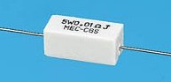
Even smaller will fit... the real thing there is 300 milivolts of voltage drop
at maximum power and the current will be 1.15A when 8 ohms are connected to the output... and twice of that when 4 ohms are connected....so... real thing is less than 700 miliwatts... even 1 watt resistance will fit.
The 5 watts value is just something standard that does not turn people suspectious that "something may be wrong" there..... more political than technicall solution...because the real thing is different.
If you have a short from colector to emitter in the associated transistor..then the current that will flow will be the supply limit...and this may be something around 8 amperes minimum during short into each rail...the small resistance (0.22 ohms) is almost a short because the huge current will flow....and if you face that sittuation, the power will be around 15 watts and will burn a 5 watts resistance anyway...so..... beeing huge as 5 watts will not be a solution in all cases..... because of that you can use 1 watt, 2 watts, 3 watts, 5 watts or 10 watts...and no one of them will be perfect to the worst case scenario.
Also the inductance is something not to bother about.... as it was considered when we think about the output coil..they work together in perfect harmony.
Yes..some guys wants non inductive resistances there...well...they believe this may result better... to me is alike to try to have milk out from stones.... no way to increase performance this way unless the idea is not to use output coil (even if you have small inductances, and capacitances in your output cable and no Radio frequency in your area)... well....if they "listen" these small differences...let it be....let them happy feeding their beliefs.... a little bit of dreams cannot be bad...we need some phantasy too...life is hard sometimes.
No matter what you do about not a perfect selection of parts you will not ruin this amplifier sonics...it is an exceptional audio amplifier wich design was made by a genius, Dr. Douglas Self...i have tweaked searching for audio performance to match my personnal taste..to tune it to my own tast...just that...but the main idea and 80 percent of the circuitry is a copy from Dr. Self design...hard to beat this one..... along 51 years searching and researching and assembling more than 6250 amplifiers i could never listen anything better...this is the top performer that made me stop to search for the perfect amplifier..this one satisfies me completelly.
Relax, be happy and be sure you gonna like it the most.
regards,
Carlos
Last edited:
Very good! No problem with the sonics but I have another question:
Is critical emitter resistors at the output to be 5W? The problem is that at my location that small and compact 5W resistors are not available. The only available are big ceramic ones like on the picture and I don't know can I squeeze them into the board. Will be a problem to use 2W resistors because they are available?
I used these resistors as emitter resistors in my Blame ES amplifier. In my Blame ST I used non inductive ones. Carlos is correct in saying their is no difference in quality of sound. My next amps will have the ceramic ones as I can get them much easier and cheaper than the other. They are a bit bigger but they can still fit(even on the TAJ boards which are smaller than the current ones).
Regards
Niss_man
Last edited:
Continuous current through the emitters resistors when testing for continuous maximum output power is not a worst case operating condition.
DX is correct when saying 1.15A cannot overheat a 0r22 emitter resistor.
But, 1.15Arms is only 10W into 8r0, not anywhere near maximum power.
For a 2pr output stage, 1.15Arms per output device is equivalent to 42W maximum power.
The peak current when delivering a maximum of 100W into 4r0 is ~7Apk.
The rated current for a 1W 0r22 resistor is ~2.13Arms
That ~7Apk is roughly 3.3times the rated current for 1W 0r22.
The peak current when delivering a worst case music signal into a 4ohm reactive speaker is ~20Apk. That is an overload of ~4.4times the rated current for a 5W 0r22.
You need to look at the overload transient ratings for your chosen resistors.
Thick wirewounds can tolerate very high overload currents without damage nor deterioration.
Metal film resistors have a much lower tolerance to overload transient currents.
I used these resistors as emitter resistors in my Blame ES amplifier. In my Blame ST I used non inductive ones. Carlos is correct in saying their is no difference in quality of sound. My next amps will have the ceramic ones as I can get them much easier and cheaper than the other. They are a bit bigger but they can still fit(even on the TAJ boards which are smaller than the current ones).
Regards
Niss_man
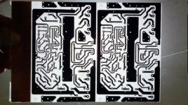
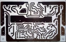
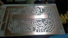
I will use the board on the picture. Are you talking for the same board (is that the TAJ board)?
If the big ceramic resistors fit in that board will be great.🙂🙂🙂
Attachments
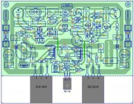
Yep this is the board (TAJ board) that I used. The resistors you want to use are the same. They will fit don't worry about that. You just have to shape the legs a bit so it doesn't interfere with any other components.
Regards
Niss_man
Regards
Niss_man
You just have to shape the legs a bit so it doesn't interfere with any other components.
I always mount high wattage resistors off the board by about 3mm using a joggle to the legs. They can glow red hot under fault conditions, and scorch the board. Must admit, though, in all the photo posts here, I've never seen it done.
Brian.
I always mount high wattage resistors off the board by about 3mm using a joggle to the legs. They can glow red hot under fault conditions, and scorch the board. Must admit, though, in all the photo posts here, I've never seen it done.
Brian.
Maybe like these ones?
http://www.diyaudio.com/forums/soli...le-build-good-amplifier-out-junk-parts-4.html
Attachments
Maybe like these ones?
Yes and no. Yes it's off the board, but no, there is no joggle in the leg to act as a stop to prevent the lead being pushed through the board and detaching a pad.
Brian.
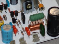
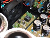
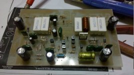
Here is a pic with the 5w ceramics in place. They are mounted off the boards as common sense. The legs have been bent to fit although they have not been joggled. I would have to be putting some serious pressure on it to detatch it from the copper tracks.
Anyway I have now found a new word for the day. "Joggle".
I tried to Joggle my wife this morning but she wouldn't have anything to do with my Joggling antics.🙂
Regards
Niss_man
Anyway I have now found a new word for the day. "Joggle".
I tried to Joggle my wife this morning but she wouldn't have anything to do with my Joggling antics.🙂
Regards
Niss_man
Attachments
Yes and no. Yes it's off the board, but no, there is no joggle in the leg to act as a stop to prevent the lead being pushed through the board and detaching a pad.
Brian.
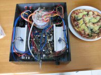
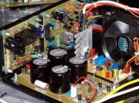
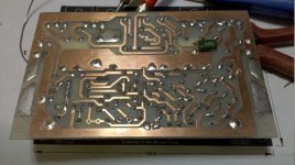
And like these LED's in the power supplies?
Did that just for fun...
http://www.diyaudio.com/forums/soli...ur-solid-state-pics-here-169.html#post2420942
Attachments
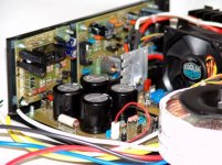
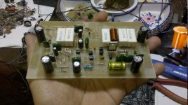
DX Blame MKII Supercharged
Hello Sir/Mr. DestroyerX,
A pleasant day to you!
Attached herewith are the photos of the DX Blame MKII Supercharged board. I have no 15 Ohms/5w on the board yet as I don't have a spare But I will add this one later.
Values changed:
1. 470R and 500R trimpot to 820R in series with 10R. Suggested values where 150R and 680R.
2. 220R was changed to 1k as suggested.
3. MJE15032/MJE15033 was changed to 2SC2073/2SA940.
4. I will be using 2SC5200 and 2SA1943 for the output transistors.
5. Supply voltage will be +/-50 Vdc @ 10 amperes with 40,000uf each rail.
I have noticed that on the board there's a room for two capacitors (C21- 470pf and C25 - 18pf). These caps are nowhere to be found on the schematic. I haven't included them yet on the actual board as well as on the simulation.
Sir DX, what will be the effect of these capacitors on the circuit?
Thanks,
Blueice23
Attachments
Dear Blame fans,
Carlos, maybe u don't like it but I add a 1K collector resistor for Q6(keep the BC546) and I can inform that it doesn't influence the sound at all
Carlos, maybe u don't like it but I add a 1K collector resistor for Q6(keep the BC546) and I can inform that it doesn't influence the sound at all
220 ohm is enough
I use 40Volt rails and u're talking about the emiter resistor I'm talking about a collector resistor
Last edited:
Very nice Blueice 23.....thank you by these pictures you have posted
these extra parts are only to the Dx Blame ES model...some guys believe it sounds better than other models..... these parts are not used in the Supercharged or in the Dx Blame ST.
Well dear Meanman.... if your solution gave a good result to you i feel happy with that.
Thank you Dado..... i am glad you are here with us.
Well boys, i am happy with you building and enjoying..about your modifications..no problem, as they do not destroy the sonics...it is hard to destroy this amplifier audio quality...it is very good.
By the way Blueice...you are very good.... great job you have done....send me picture from you directly to:
nanabrother@hotmail.com
Picture is for the Dx Corporation's hall of fame..if you dislike to see it published, them let me know and i will keep it to myself only.
Smartx21 have made a great job too...nice work Max....congratulations!
regards,
Carlos
Last edited:
these extra parts are only to the Dx Blame ES model...some guys believe it sounds better than other models..... these parts are not used in the Supercharged or in the Dx Blame ST.
By the way Blueice...you are very good.... great job you have done....send me picture from you directly to:
nanabrother@hotmail.com
Picture is for the Dx Corporation's hall of fame..if you dislike to see it published, them let me know and i will keep it to myself only.
regards,
Carlos
Hello Mr. DX sir,
I am most grateful having built the amplifier you made. Saying thank you is not enough for this wonderful gift you have shared. I will send you the photos as instructed and you can freely publish it. Thank you as you have appreciated my work as well.
By the way, I have tested the amp last night, directly driven by the CD player (no tone controls)and I never thought this unit can really deliver great Sonics. My 8" sub had never played vocals like the way it did before with other amps. My wife and Mom liked the way it sounds. This artwork is something I will treasure. I will build more of this amp and give it to my Brother and Grandma for them to hear great music.
Once again, many thanks to you Mr. DX sir!
Humbly yours,
Blueice23
I am very glad you have appreciated
Good idea to produce more amplifier for your family.
regards,
Carlos
Good idea to produce more amplifier for your family.
regards,
Carlos
I use 40Volt rails and u're talking about the emiter resistor I'm talking about a collector resistor
I am tolking about collector resistor too.
- Status
- Not open for further replies.
- Home
- Amplifiers
- Solid State
- Dx Blame ST - Builder's thread - post pictures, reviews and comments here please.