post1198: Vbe multiplier.
The r20 value of 150r is a bit low.
The minimum voltage from the multiplier is Vbe * [1+ {2200 / (150+1k0)}] = ~1.75V when Vbe=600mV
The maximum voltage from the multiplier is ~9.4V when VR (P1) is adjusted to 0r0.
I think 9.4V for a maximum Vbias is far too high and invites heat damaging accidents.
I also think the minimum voltage is just a little bit high. It exceeds four Vbe=400mV to ensure the drivers and outputs are turned off when set to minimum.
Have a think about returning R19 to 2k0 and making R20 = 330r or 360r and retain 1k for VR.
This gives a Vbias range of to 1.6V to 4.6V if Vbe=600mV
In addition, I recommend that VR be set to maximum of 1k and checked with a resistance meter for first power up (via a bulb limiter).
post1198: Vbe multiplier.
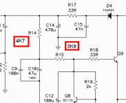
Carlos seems to be using the same 2.2k / 680 /150R Vbe that I do. The only difference is that I trim the 150R (200R). With just the 200R as adjustment , I can go from 0 mv Re at 2 turns into the 200R to over 40mv Re "all the way" ( 0mA - 200+ mA Re) ... this is at 40-45V rails. At 75-80v rails , the biggest factor to match the lower voltage bias range is the total current in the VAS determined by the 2 bootstrap resistors (R14/15). My scheme is 3.3k/3.3k @ 40V and 4.7k/6.8k at 70V+ , I would say that 3.3K/4.7K would give the 6ma+ at the VAS for 50-55 V rails. I do not speculate , as I have a blame ES style voltage board that I have used for months now on both my 40 and 75V output stages. On the 75v stage the ES is "scary" in it's dynamics and range .... it works VERY good at 200W+ / 8R , REALLY "super- duper" charged. 😀
BTW , to reduce the "top" resistor to 2k changes the compensation ratio , I tried it. At 2k , the amp had a greater "spread" in mV Re (13-18mV) as opposed to the 2.2k (15-17mV). These tests were done from the amp in the snow 😀 all the way to max hairdryer temp. ( 10 -50+ C)
OS
I think you have measured the effect of the not quite constant current passing through the Vbe multiplier.........BTW , to reduce the "top" resistor to 2k changes the compensation ratio , I tried it. At 2k , the amp had a greater "spread" in mV Re (13-18mV) as opposed to the 2.2k (15-17mV). These tests were done from the amp in the snow 😀 all the way to max hairdryer temp. ( 10 -50+ C)
Converting the multiplier to use the extra Self resistor, minimises multiplier voltage change (constant Vbias) for small changes in multiplier current.
Further, the current through the resistor string must swamp the current from/to the base of the multiplier. hFE of the multiplier affects this a lot.
Let's take an example.
R19=2k2, R20=680, hFE=80, VAS bias 8mA, Vbias~2.54V when Vbe=600mV
R20 has ~600mV across it and passes ~880uA
Ie must be 8000uA-880uA =7120uA
Ib must be 89uA
Ir19 must be 880uA-89uA=791uA.
A small change in multiplier current changes all these current values and thus changes Vbias. This is why the bootstrap or the CCS controlling VAS current must work effectively at holding near constant VAS current.
This can be improved in three ways.
increase the current in the resistor string.
or
increase hFE of the multiplier
or
add the Self resistor
or any combination of these 3.
using these as a guide
I would adopt
R19=1k2, R20=371, hFE=200, VAS bias=8mA, Self resistor ~16r
Would you like to simulate how Vbias varies for these two arrangements when VAS current changes +-5%.
Last edited:
So we have found the same values Ostripper
There are many roads and all them go to Rome...old say this one.
I am not happy with my second VAS....it is a little bit hot to my taste...i will try a small U shape heatsink on it.... interesting, these things worries me a lot.
regards,
Carlos
There are many roads and all them go to Rome...old say this one.
I am not happy with my second VAS....it is a little bit hot to my taste...i will try a small U shape heatsink on it.... interesting, these things worries me a lot.
regards,
Carlos
Sorry for this small intrusion...
Hi, robydream!
I really live in southern Brazil, and this is a folk music from my state, which is called Rio Grande do Sul, with strong influence from neighbour countries, as Carlos stated in his reply.
I find nice you loving this song, as much as I admire Plitvička Jezera!!!!!!!!!!
Its author's name is "LUIZ MARENCO", and its name is "BATENDO ÁGUA", where "água" means "WATER"!!!!! Something like "tapping on water" or "raining too much". This is the instrumental version, but you can find the original part searching for those names under Emule or other MP3 downloader, and also on YouTube. Some history here: Luiz Marenco and lyrics here: http://letras.terra.com.br/luiz-marenco/1309838/
All the best!
Max.
thanks..for Dx Blame ST youtube link..i im currently waiting...for parts delivery from mouser.
Could you tell me what is that song that is playing on Prazer na sala de estar?
It sounds very nice, and i love it.
regards, to all diy builders...🙂
Hi, robydream!
I really live in southern Brazil, and this is a folk music from my state, which is called Rio Grande do Sul, with strong influence from neighbour countries, as Carlos stated in his reply.
I find nice you loving this song, as much as I admire Plitvička Jezera!!!!!!!!!!
Its author's name is "LUIZ MARENCO", and its name is "BATENDO ÁGUA", where "água" means "WATER"!!!!! Something like "tapping on water" or "raining too much". This is the instrumental version, but you can find the original part searching for those names under Emule or other MP3 downloader, and also on YouTube. Some history here: Luiz Marenco and lyrics here: http://letras.terra.com.br/luiz-marenco/1309838/
All the best!
Max.
Attachments

Last edited:
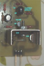
Heat scares me....when it i around 38...even 40 is acceptable
But when increases to 44 i few myself in panic.....well....this is me...i know that others do not mind about that....well, will try a tiny heatsink to this MJE15030 (second VAS):
YouTube - Heat bothers me...muito quente esse cara
regards,
Carlos
But when increases to 44 i few myself in panic.....well....this is me...i know that others do not mind about that....well, will try a tiny heatsink to this MJE15030 (second VAS):
YouTube - Heat bothers me...muito quente esse cara
regards,
Carlos
Attachments
But when increases to 44 i few myself in panic.....well....this is me...i know that others do not mind about that....well, will try a tiny heatsink to this MJE15030 (second VAS):
YouTube - Heat bothers me...muito quente esse cara
regards,
Carlos
I can't understand why it would be that hot ? 😕 ES/ST VAS can't be more than 6-7ma. Without HS , 32C was max ... with PCB heatsink (below) , maybe 2-3C above the room temperature. I even use a little to-126 , still ... just a little heat.
OS
Attachments
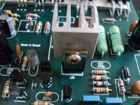
I also could not understand...well...if we do not know the causes of a
disease....at least we know the medicine to reduce temperature...i have installed a heatsink too...will try one alike yours.
Usually i am having 35 volts in the supply....so..maximum peak to peak is not so big...now i am having more than 55 volts.... this increased the heat....usually my amplifier does not use heatsinks to the VAS....i do think this one is needing...i will suggest folks to use a tiny aluminium blade.... a thin foil... these thin ones used by comercial amplifiers down the eigthies.... so...a rectangular piece of 6 by 2 centimeters, folded in U shape may work well too.
regards,
Carlos
Attachments
Last edited:
disease....at least we know the medicine to reduce temperature...i have installed a heatsink too...will try one alike yours.
Usually i am having 35 volts in the supply....so..maximum peak to peak is not so big...now i am having more than 55 volts.... this increased the heat....usually my amplifier does not use heatsinks to the VAS....i do think this one is needing...i will suggest folks to use a tiny aluminium blade.... a thin foil... these thin ones used by comercial amplifiers down the eigthies.... so...a rectangular piece of 6 by 2 centimeters, folded in U shape may work well too.
regards,
Carlos
You are trying to cure the "fever" , not the disease....
When you raise rail voltage to 55 , VAS current increases .. throwing temperature and bias off.
(pix1) is ES/ST clone at your 3.3k/2.7k bootstrap network , 5.8-6.0ma @ 35v rails.
(pix2) , raise rails to 55v ... 9.1ma. This MIGHT heat up the VAS device with large voltage swings.
(pix3) is the "corrected" VAS , back down to 6.0--6.3ma with 4.7k/4.7k as the bootstrap resistors. I had to even increase these to 6.8k/4.7k for 75v rails to keep my 6ma.
PS . CCS VAS does not have this issue , non-bootstrap will stay 6.02mA all the way from 30-75v.
OS
Attachments
Last edited:
Off course bootstrap resistances where increased
Come on Ostripper, uncle charlie is doing these things since 1960.
Sometimes i say "i don't know" to shorten the answer.
55V multiplied by 0.006A results im more heat than 35V multiplied by 0.006A...i meant something simple like that....also, dinamically we have more audio swing
regards,
Carlos
Come on Ostripper, uncle charlie is doing these things since 1960.
Sometimes i say "i don't know" to shorten the answer.
55V multiplied by 0.006A results im more heat than 35V multiplied by 0.006A...i meant something simple like that....also, dinamically we have more audio swing
regards,
Carlos
Attachments
Last edited:
Hi, robydream!
I really live in southern Brazil, and this is a folk music from my state, which is called Rio Grande do Sul, with strong influence from neighbour countries, as Carlos stated in his reply.
I find nice you loving this song, as much as I admire Plitvička Jezera!!!!!!!!!!
Its author's name is "LUIZ MARENCO", and its name is "BATENDO ÁGUA", where "água" means "WATER"!!!!! Something like "tapping on water" or "raining too much". This is the instrumental version, but you can find the original part searching for those names under Emule or other MP3 downloader, and also on YouTube. Some history here: Luiz Marenco and lyrics here: BATENDO ÁGUA - LUIZ MARENCO (letra e vídeo)
All the best!
Max.
Thank you very much...i really love it...i found it...🙂 Plitvička Jezera is very good....i see you like natures park..🙂
Never saw the "chart", DX. I wasn't even born in 1960.. 😀
Still , even a larger voltage swing should not heat a "monster" like the MJE15032... EVEN at 10ma. 😕 Current stays within .3ma even at 120v p-p
Little 2sa1381 with 100v p-p swings stays coooool !!
OS
Still , even a larger voltage swing should not heat a "monster" like the MJE15032... EVEN at 10ma. 😕 Current stays within .3ma even at 120v p-p
Little 2sa1381 with 100v p-p swings stays coooool !!
OS
Nice this transistor
I am shocked....not because of your transistor...i will have to eat 5 digital cameras i have bought...that cheap Spy Pen camera is producing better videos with better audio.....grrrrrr!....shocked!
YouTube - 1280x960 pen camera test video 05
http://www.youtube.com/watch?v=Kw2C27aD_s8&NR=1&feature=fvwp
20 bucks!....grrrrrr!
regards,
Carlos
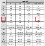
Attention.... VAS emitter resistance needs replacement in the Supercharged
here you have more details:
http://www.diyaudio.com/forums/soli...mkii-supercharged-release-37.html#post2429305
regards,
Carlos
here you have more details:
http://www.diyaudio.com/forums/soli...mkii-supercharged-release-37.html#post2429305
regards,
Carlos
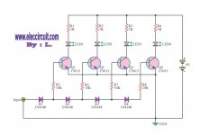
Dx power meter - untested 50 watts version
This was only simulated...for sure will need some resistance adjustment to match led brightness and to adjust the ligthing threshold point.
This is not a measurement instrument, it is just a gadget to you to have fun....led operates in a range of brigthness, so, you have one different value of indication when the brigth is dim or strong...current is around 6,5 miliamperes to full power input.
It can be used into speaker panels or inside power amplifier enclosure.....do not need supply....audio is rectified, filtered and, as consequence, converted to DC.... an audio feeded device that will drain around 56 miliamperes from your power amplifier output signal.... if you use 4 ohms, then multiply by two your power readings.
Consumption will depend on your output power...can go from a couple of miliamperes to around 60 millamperes...you can use other condenser value if you want... these input resistances are protection, alike fusistors.... it should burn if you experience a short into your bridge rectifier (this happens)...then use 1.4 watts resistances..they are there to burn easy and fast..also to provide a minimum load to the power amplifier if you have your rectifier bridge or diodes shorted..then they will burn and circuit will be opened to the power amplifier output... fuses are welcome..but small resistances will do the job too.
I have tested the 100 watts version and i do not have any fear about the circuit...led brigthness should be retouched if you decide to use other colours...not only the ligthing threshold but also the brigthness may need resistance tweaking.
The Corporation accept, gladly, suggestions to improve...but using simple discrete components....we do not want CCS, or fets, or chips, or complicated stuff....this is a toy and should continue to be DIY, a gadget, for free and for fun and directed to uncle charlie diy friends.
Internet has a lot of circuits with dedicated chips....so....there you may find something more serious if you need.....this one is nice because simple, easy to be made and will work without troubles if you are not too much demanding about precision.....a gadget fellows!
regards,
Carlos
Attachments
Last edited:
If I were to make one , (below) would be where I would start. Divide the input down with a few resistors to scale the readout to the amp ... done. To slow (average) the response time , add a cap to make the input divider have a R/C constant.
I would add a 470k pull down resistor from each base to ground for more reliable led switching. 🙂
OS
I would add a 470k pull down resistor from each base to ground for more reliable led switching. 🙂
OS
Attachments
I have made a prototype...soon video here
Good idea Ostry....will you build to show us?....will be good to have this other one posted here too....maybe a BX meter version
regards,
Carlos
Good idea Ostry....will you build to show us?....will be good to have this other one posted here too....maybe a BX meter version
regards,
Carlos
Hi Uncle Charlie.😀
An externally hosted image should be here but it was not working when we last tested it.
Yep Kanwar....we look alike
He also likes girls!
hehehehe...
here is the gadget...will be nice at night:
http://www.youtube.com/watch?v=5OwRe73rn2g
regards,
Carlos
He also likes girls!
hehehehe...
here is the gadget...will be nice at night:
http://www.youtube.com/watch?v=5OwRe73rn2g
regards,
Carlos
Last edited:
- Status
- Not open for further replies.
- Home
- Amplifiers
- Solid State
- Dx Blame ST - Builder's thread - post pictures, reviews and comments here please.